Reinforcement Detailing of Reinforced Concrete Slabs
Reinforcement detailing of a slab is done based on its support conditions. Slab may be supported on walls or beams or columns. Slab supported directly by columns are called flat slab.
Slab supported on two sides and bending takes place predominantly in one direction only is called One Way Slab. On the other hand, when slab is supported on all four sides and bending take place in two directions are said to be Two Way Slab.
The slabs having ratio of longer length to its shorter length (Ly/Lx) greater than 2 is called one way slab otherwise as two way slab. In one way slab main reinforcement is parallel to shorter direction and the reinforcement parallel to longer direction is called distribution steel. In two way slab main reinforcement is provided along both direction.
Slabs could be simply supported, continuous or cantilever. In two way slab the corners may be held down by restraints or may be allowed to lift up. Additional torsion reinforcement is required at corners when it is restrained against uplifting as shown in Fig.1.
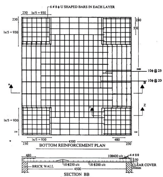
Thickness of the slab is decided based on span to depth ratio specified in IS456-2000. Minimum reinforcement is 0.12% for HYSD bars and 0.15% for mild steel bars. The diameter of bar generally used in slabs are: 6 mm, 8 mm, 10 mm, 12mm and 16mm.
The maximum diameter of bar used in slab should not exceed 1/8 of the total thickness of slab. Maximum spacing of main bar is restricted to 3 times effective depth or 300 mm whichever is less. For distribution bars the maximum spacing is specified as 5 times the effective depth or 450 mm whichever is less.
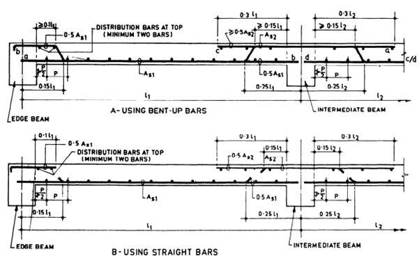
Minimum clear cover to reinforcements in slab depends on the durability criteria and this is specified in IS 456-200. Generally 15mm to 20mm cover is provided for the main reinforcements. Alternate main bars can be cranked near support or could be bent at 1800at the edge and then extended at the top inside the slab as shown in Fig.1. Curtailment and cranking of bars and is shown in Fig. 2.
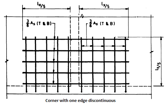
Torsion reinforcement shall be provided at any corner where the slab is simply supported on both edges meeting at that corner and is prevented from lifting unless the consequences of cracking are negligible. It shall consist of top and bottom reinforcement, each with layer of bars placed parallel to the sides of the slab and extending from the edges a minimum distance of one fifth of the shorter span.
The area of reinforcement per unit width in each of these four layers shall be three quarters of the area required for the maximum midspan moment per unit width in the slab.
Torsion reinforcement equal to half that described above shall be provided at a corner contained by edges over only one of which the slab is continuous. Torsion reinforcement to be provided is shown in Fig. 3 below.

The drawing showing the detailing of reinforcement has a plan showing typical reinforcement in both direction and sectional elevations. Typical detailing of slab is shown in Fig.4 and 5.
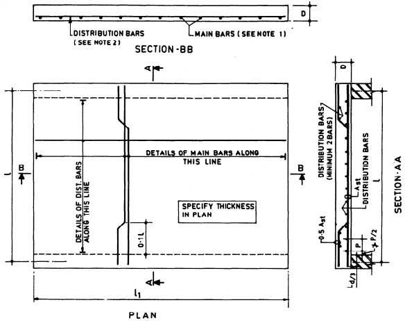 Fig.4: Slab spanning in one direction (One-way slab)
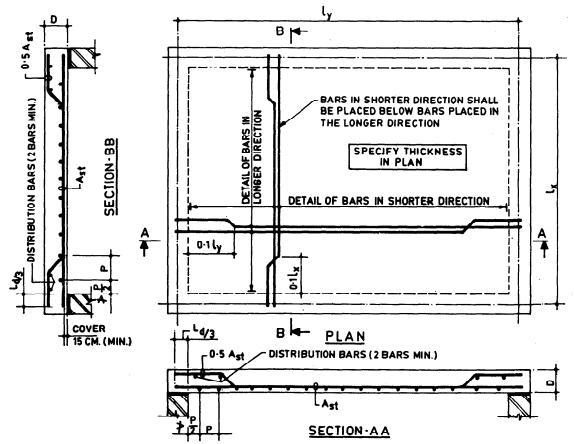 Fig.5: Slab spanning in two-directions (two-way slab)
No comments:
Post a Comment