Highway Surface Drainage System and Its Design
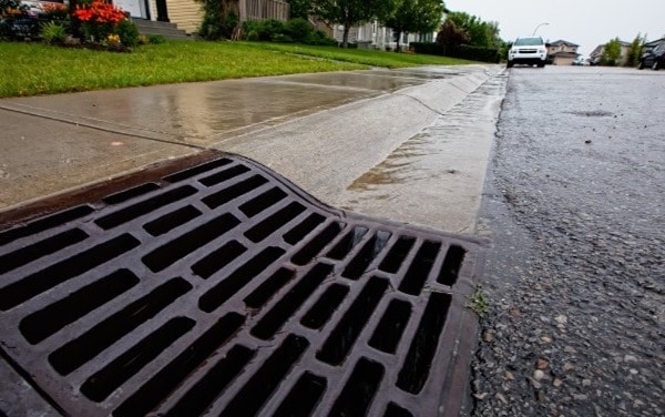
Surface drainage system is most important in Highway engineering. A pavement without proper drainage facilities will not serve for long time. The water or rainfall on road should be collected by side drains which carries the drain water to nearest stream or any water course.
So, prior to the construction of road, the designer should leave required space for providing proper drainage facilities as well as the pavement should also be constructed with minimum camber.

Design of Surface Drainage System for Highway
The design of surface drainage system carried by two types of analysis:
- Hydrologic analysis
- Hydraulic analysis
Hydrologic Analysis of Drainage for Highway
Whenever there is a rainfall, some of the rain water infiltrated into the ground and stored as ground water and some of the portion may evaporate into the atmosphere. Other than these losses, the water left on the surface is called as run off.
The method of estimating the run off is called hydrologic analysis. To estimate the maximum quantity of water expected to reach the drainage system is the main objective of hydrologic analysis. For this, one need to know the factors affecting run off and they are
- Rate of rain fall
- Moisture condition
- Soil type
- Ground cover presence
- Topography
Other than the above factors, rain fall intensity, occurrence of storms in that area are to be studied from the old records. Hence, maximum run off can be estimated to build safe surface drainage system. The run off can be calculated by below formula
Q = C i Ad
Where Q = run off (m3/sec)
C = run off coefficient
i = intensity of rain fall (mm/sec)
Ad = area of drainage (m2)

Run off coefficient “C” is the ratio of run off to the rate of rainfall. So, it is not same for all types of surfaces. It varies for different types of surfaces and its values for different surfaces are as follows:
| Type of Surface | Coefficient of run off |
| Pervious soil surface | 0.05 – 0.30 |
| Soil covered with turf | 0.30 – 0.55 |
| Impervious soil | 0.40 – 0.65 |
| Gravel & WBM roads | 0.35 – 0.70 |
| Bituminous & C.C roads | 0.80 – 0.90 |
If the drainage area contains different surfaces in it then run off coefficient is calculated as
C = (A1 C1+A2 C2+A3 C3) / (A1+A2+A3)
Where C1, C2, C3 are run off coefficients for different surfaces and A1, A2, A3 are their respective areas.
In the Next stage, Intensity of rainfall “i” is to be calculated. To find this, first we need to know the time taken by water to reach drainage inlet from the drainage area. This can be found out from the below graph. This is called as inlet time.

Now we need to calculate the time required for water to travel from inlet of drainage to the outlet which is called as travel time This is calculated from the velocity allowed in the drainage line and generally it is kept at 0.3 – 1.5 m/sec.
After that both times (inlet time and travel time) are added which finally gives us the time of concentration. From this total duration, read the rain fall intensity from the below graph by assuming frequency of rainfall occurrence (say for 5 years, 10 years etc.)

Lastly area of drainage is calculated by studying on the topographical maps of that region. Hence, the design value of run off “Q” is obtained finally.

Hydraulic Analysis of Highway Drains
Now comes the second stage hydraulic analysis, in which the dimensions of drainage channels or culverts are designed based on “Q” obtained in the above stage of analysis. Now we have discharge which is designed run off “Q”.
If we know the allowable velocity “V” in the channel, then the area of channel can be calculated from below formula:
Q = A.V
But the allowable velocity is not same for all types of channels. If the channel is lined, then the allowable velocity can be kept at normal. But if the channel is unlined it may cause severe damage to the channel in the form of silting or scouring.
So, the allowable velocity for different cases of unlined materials is as follows:
| Soil type | Allowable velocity (m/sec) |
| Sand or silt | 0.30 – 0.50 |
| Loam | 0.60 – 0.90 |
| Clay | 0.90 – 1.50 |
| Gravel | 1.20 – 1.50 |
| Soil with grass | 1.50 – 1.80 |

Now we can find out the area of channel in m2. Next, the longitudinal slope of channel “S” is to be calculated by Manning’s formula:
Where V = Allowable velocity (m/sec)
N = Manning’s roughness coefficient
R = Hydraulic radius (m)
S= Longitudinal slope of channel
In the above formula, we already know the “V” value. Hydraulic radius “R” is the ratio of area of the channel to its wetted perimeter. Now comes, the toughness coefficient which is again varies according to lining material as follows:
| Lining material | Manning’s roughness coefficient, n |
| Ordinary soil | 0.02 |
| Soil with grass layer | 0.05 – 0.10 |
| Concrete lining | 0.013 |
| Rubble lining | 0.04 |
Finally, longitudinal slope “S” is known and all the dimensions of drainage channel are known. Thus, the design of surface drainage system is complete. This method is mostly used for designing side drains of roads.

No comments:
Post a Comment