Components of a Hydropower Plant and their Functions
What is Hydropower Plant?
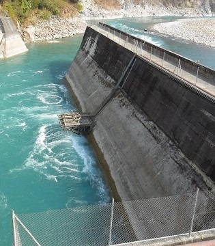
Hydropower plant uses hydraulic energy of water to produce electricity. The power obtained from this plant is termed as hydroelectric power. Nearly 16% of total power used by the world is represented by hydropower.
There are several types of hydropower plants classified on different characteristics. But for every hydropower plant some important principal components are needed and those are explained here.
Components of a Hydropower Plant
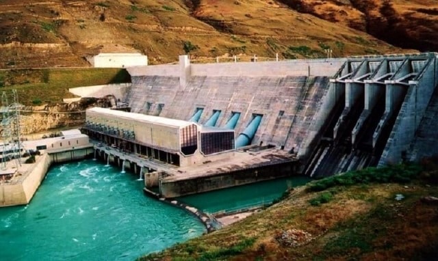
The major components of a hydroelectric plant are as follows.
- Forebay
- Intake structure
- Penstock
- Surge chamber
- Hydraulic turbines
- Power house
- Draft tube
- Tailrace
Forebay
A forebay is a basin area of hydropower plant where water is temporarily stored before going into intake chamber. The storage of water in forebay is decided based on required water demand in that area. This is also used when the load requirement in intake is less.
We know that reservoirs are built across the rivers to store the water, the water stored on upstream side of dam can be carried by penstocks to the power house. In this case, the reservoir itself acts as forebay.
Intake Structure
Intake structure is a structure which collects the water from the forebay and directs it into the penstocks. There are different types of intake structures are available and selection of type of intake structure depends on various local conditions.
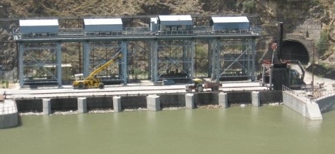
Intake structure contain some important components of which trash racks plays vital role. Trash racks are provided at the entrance of penstock to trap the debris in the water.
If debris along with water flows into the penstock it will cause severe damage to the wicket gates, turbine runners, nozzles of turbines etc. these trash racks are made of steel in rod shape. These rods are arranged with a gap of 10 to 30cm apart and these racks will separate the debris form the flowing water whose permissible velocity is limited 0.6 m/sec to 1.6 m/sec.
In cold weather regions, there is chance of formation of ice in water, to prevent the entrance of ice into the penstocks trash racks heated with electricity and hence ice melts when it touches the trash racks.
Other than trash racks, rakes and trolley arrangement which is used to clean the trash racks and penstock closing gates are also provided in intake structure.
Penstock
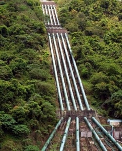
Penstocks are like large pipes laid with some slope which carries water from intake structure or reservoir to the turbines. They run with some pressure so, sudden closing or opening of penstock gates can cause water hammer effect to the penstocks.
So, these are designed to resist the water hammer effect apart from this penstock is similar to normal pipe. To overcome this pressure, heavy wall is provided for short length penstock and surge tank is provided in case of long length penstocks.
Steel or Reinforced concrete is used for making penstocks. If the length is small, separate penstock is used for each turbine similarly if the length is big single large penstock is used and at the end it is separated into branches.
Surge Chamber
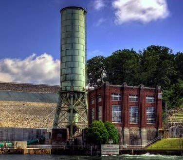
A surge chamber or surge tank is a cylindrical tank which is open at the top to control the pressure in penstock. It is connected to the penstock and as close as possible to the power house.
Whenever the power house rejected the water load coming from penstock the water level in the surge tank rises and control the pressure in penstock.
Similarly, when the huge demand is needed in power house surge tank accelerates the water flow into the power house and then water level reduces. When the discharge is steady in the power house, water level in the surge tank becomes constant.
There are different types of surge tanks available and they are selected based on the requirement of plant, length of penstock etc.
Hydraulic Turbines
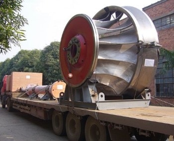
Hydraulic turbine, a device which can convert the hydraulic energy into the mechanical energy which again converted into the electrical energy by coupling the shaft of turbine to the generator.
The mechanism in this case is, whenever the water coming from penstock strike the circular blades or runner with high pressure it will rotate the shaft provided at the center and it causes generator to produce electrical power.
Generally hydraulic turbines are of two types namely
- Impulse turbine
- Reaction turbine
Impulse turbine is also called as velocity turbine. Pelton wheel turbine is example for impulse turbine. Reaction turbine is also called as pressure turbine. Kaplan turbine and Francis turbine come under this category.
Power House
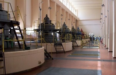
Power house is a building provided to protect the hydraulic and electrical equipment. Generally, the whole equipment is supported by the foundation or substructure laid for the power house.
In case of reaction turbines some machines like draft tubes, scroll casing etc. are fixed with in the foundation while laying it. So, the foundation is laid in big dimensions.
When it comes to super structure, generators are provided on the ground floor under which vertical turbines are provided. Besides generator horizontal turbines are provided. Control room is provided at first floor or mezzanine floor.
Draft Tube
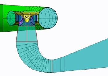
If reaction turbines are used, then draft tube is a necessary component which connects turbine outlet to the tailrace. The draft tube contains gradually increasing diameter so that the water discharged into the tailrace with safe velocity. At the end of draft tube, outlet gates are provided which can be closed during repair works.
Tailrace
Tailrace is the flow of water from turbines to the stream. It is good if the power house is located nearer to the stream. But, if it is located far away from the stream then it is necessary to build a channel for carrying water into the stream.
Otherwise the water flow may damage the plant in many ways like lowering turbine efficiency, cavitation, damage to turbine blades etc.
This is because of silting or scouring caused by unnecessary flow of water from power house. Hence, proper design of tailrace should be more important.
