What is a Pelton Turbine?
Pelton Turbine is a Tangential flow impulse turbine in which the pressure energy of water is converted into kinetic energy to form high speed water jet and this jet strikes the wheel tangentially to make it rotate. It is also called as Pelton Wheel.
Parts and Their Functions of Pelton Turbine
Different parts and their functions of Pelton turbine are as follows.
1.Nozzle and Flow Regulating Arrangement
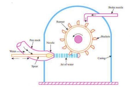
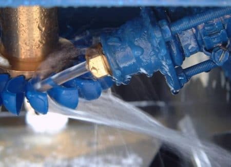
The water from source is transferred through penstock to which end a nozzle is provided. Using this nozzle the high speed water jet can be formed. To control the water jet from nozzle, a movable needle spear is arranged inside the nozzle.
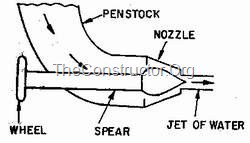
The spear will move backward and forward in axial direction. When it is moved forward the flow will reduce or stopped and when it is moved backward the flow will increase.
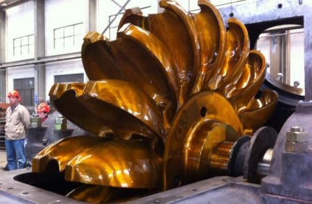
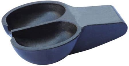
2.Runner and Buckets
A Pelton turbine consists of a runner, which is a circular disc on the periphery of which a number of buckets are mounted with equal spacing between them. The buckets mounted are either double hemispherical or double ellipsoidal shaped.
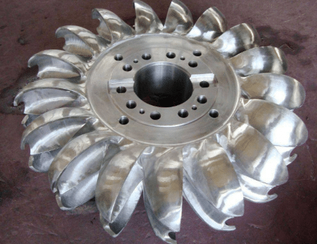
A dividing wall called splitter is provided for each bucket which separates the bucket into two equal parts. The buckets are generally made of cast iron or stainless steel or bronze depending upon the head of inlet of Pelton turbine.
3.Casing
The whole arrangement of runner and buckets, inlet and braking jets are covered by the Casing. Casing of Pelton turbine does not perform any hydraulic actions but prevents the splashing of water while working and also helps the water to discharge to the tail race.

4.Braking Jet
Braking jet is used to stop the running wheel when it is not working. This situation arises when the nozzle inlet is closed with the help of spear then the water jet is stopped on the buckets. But Due to inertia, the runner will not stop revolving even after complete closure of inlet nozzle.
To stop this, a brake nozzle is provided as shown in figure 1. The brake nozzle directs the jet of water on the back of buckets to stop the wheel. The jet directed by brake nozzle is called braking jet.
Working of Pelton Turbine
The working of Pelton turbine is as follows:
- The water is transferred from the high head source through a long conduit called Penstock.
- Nozzle arrangement at the end of penstock helps the water to accelerate and it flows out as a high speed jet with high velocity and discharge at atmospheric pressure.
- The jet will hit the splitter of the buckets which will distribute the jet into two halves of bucket and the wheel starts revolving.
- The kinetic energy of the jet is reduced when it hits the bucket and also due to spherical shape of buckets the directed jet will change its direction and takes U-turn and falls into tail race.
- In general, the inlet angle of jet is in between 1o to 3o, after hitting the buckets the deflected jet angle is in between 165o to 170o.
- The water collected in tail race should not submerge the Pelton wheel in any case.
- To generate more power, two Pelton wheels can be arranged to a single shaft or two water jets can be directed at a time to a single Pelton wheel.
Design aspects of Pelton Turbine
Following are the aspects to be considered while designing the Pelton wheel turbine.
- Velocity of jet
- Velocity of wheel
- Angle of deflection of jet
- Mean diameter of the wheel
- Jet ratio
- Bucket dimensions
- Number of jets
- Number of buckets
1.Velocity of Jet
The velocity of the jet at inlet is given by
Where Cv = co-efficient of velocity =0.98 or 0.99.
H= Net head on turbine.
2.Velocity of Wheel
The velocity of wheel (u) is given by
Where,  = speed ratio = 0.43 to 0.48
3.Angle of Deflection of Jet
The angle of deflection of jet after striking the buckets is taken as 165o if no deflection angle is given.
4.Mean Diameter of The Wheel
The mean diameter or the pitch diameter D of the pelton turbine is given by
5.Jet Ratio
It is defined as the ratio of the pitch diameter (D) of the pelton turbine to the diameter of the jet (d). It is denoted by m and is given as
m = D/d
Jet ratio(m) is lies between 11 to 16 for maximum hydraulic efficiency. however, In most of the cases it is taken as 12.
6.Bucket Dimensions
Buckets dimensions are designed in such a way that its breadth should be 3 to 4 times of diameter of jet, length should be 2 to 3 times of diameter of jet and thickness should be 0.8 to 1.2 times the diameter of jet.
7.Number of Jets
It is obtained by dividing the total rate of flow through the turbine by the rate of flow of water through a single jet.
In general, Number of jets are limited to two in case of vertical runner and six in case of horizontal runner.
8.Number of Buckets
The number of buckets (z) on a runner is given by
Where, D = Pitch diamater
d = Diameter of Jet
m = jet ratio
No comments:
Post a Comment