Methods of Rainwater Harvesting -Components, Transport and Storage
Methods of Rainwater Harvesting
Broadly there are two ways of harvesting rainwater
- Surface runoff harvesting
- Roof top rainwater harvesting
Rainwater harvesting is the collection and storage of rainwater for reuse on-site, rather than allowing it to run off. These stored waters are used for various purposes such as gardening, irrigation etc. Various methods of rainwater harvesting are described in this section.
1. Surface runoff harvesting
In urban area rainwater flows away as surface runoff. This runoff could be caught and used for recharging aquifers by adopting appropriate methods.
2. Rooftop rainwater harvesting
It is a system of catching rainwater where it falls. In rooftop harvesting, the roof becomes the catchments, and the rainwater is collected from the roof of the house/building. It can either be stored in a tank or diverted to artificial recharge system. This method is less expensive and very effective and if implemented properly helps in augmenting the groundwater level of the area.
Rooftop Rainwater Harvesting System
Components of the Rooftop Rainwater Harvesting
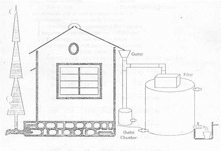
The illustrative design of the basic components of roof top rainwater harvesting system is given in the typical schematic diagram shown in Fig 1.

Fig 1: Components of Rainwater Harvesting
The system mainly constitutes of following sub components:
- Catchments
- Transportation
- First flush
- Filter
Catchments
The surface that receives rainfall directly is the catchment of rainwater harvesting system. It may be terrace, courtyard, or paved or unpaved open ground. The terrace may be flat RCC/stone roof or sloping roof. Therefore the catchment is the area, which actually contributes rainwater to the harvesting system.
Transportation
Rainwater from rooftop should be carried through down take water pipes or drains to storage/harvesting system. Water pipes should be UV resistant (ISI HDPE/PVC pipes) of required capacity. Water from sloping roofs could be caught through gutters and down take pipe. At terraces, mouth of the each drain should have wire mesh to restrict floating material.
First Flush
First flush is a device used to flush off the water received in first shower. The first shower of rains needs to be flushed-off to avoid contaminating storable/rechargeable water by the probable contaminants of the atmosphere and the catchment roof. It will also help in cleaning of silt and other material deposited on roof during dry seasons Provisions of first rain separator should be made at outlet of each drainpipe.
Filter
There is always some skepticism regarding Roof Top Rainwater Harvesting since doubts are raised that rainwater may contaminate groundwater. There is remote possibility of this fear coming true if proper filter mechanism is not adopted.
Secondly all care must be taken to see that underground sewer drains are not punctured and no leakage is taking place in close vicinity.
Filters are used for treatment of water to effectively remove turbidity, colour and microorganisms. After first flushing of rainfall, water should pass through filters. A gravel, sand and ‘netlon’ mesh filter is designed and placed on top of the storage tank. This filter is very important in keeping the rainwater in the storage tank clean. It removes silt, dust, leaves and other organic matter from entering the storage tank.
The filter media should be cleaned daily after every rainfall event. Clogged filters prevent rainwater from easily entering the storage tank and the filter may overflow. The sand or gravel media should be taken out and washed before it is replaced in the filter.
A typical photograph of filter is shown in Fig 2.


Fig 2: Photograph of Typical Filter in Rainwater Harvesting
There are different types of filters in practice, but basic function is to purify water. Different types of filters are described in this section.
Sand Gravel Filter
These are commonly used filters, constructed by brick masonry and filleted by pebbles, gravel, and sand as shown in the figure. Each layer should be separated by wire mesh. A typical figure of Sand Gravel Filter is shown in Fig 3.


Fig 3: Sand Gravel Filter
Charcoal Filter
Charcoal filter can be made in-situ or in a drum. Pebbles, gravel, sand and charcoal as shown in the figure should fill the drum or chamber. Each layer should be separated by wire mesh. Thin layer of charcoal is used to absorb odor if any. A schematic diagram of Charcoal filter is indicated in Fig 4.


Fig 4: Charcoal Filter
PVC –Pipe filter
This filter can be made by PVC pipe of 1 to 1.20 m length; Diameter of pipe depends on the area of roof. Six inches dia. pipe is enough for a 1500 Sq. Ft. roof and 8 inches dia. pipe should be used for roofs more than 1500 Sq. Ft. Pipe is divided into three compartments by wire mesh.
Each component should be filled with gravel and sand alternatively as shown in the figure. A layer of charcoal could also be inserted between two layers. Both ends of filter should have reduce of required size to connect inlet and outlet. This filter could be placed horizontally or vertically in the system. A schematic pipe filter is shown in Fig 5.


Fig 5: PVC-Pipe filter
Sponge Filter
It is a simple filter made from PVC drum having a layer of sponge in the middle of drum. It is the easiest and cheapest form filter, suitable for residential units. A typical figure of sponge filter is shown in Fig 6.


Fig 6: Sponge Filter
Methods of Rooftop Rainwater Harvesting
Various methods of using roof top rainwater harvesting are illustrated in this section.
a) Storage of Direct Use
In this method rainwater collected from the roof of the building is diverted to a storage tank. The storage tank has to be designed according to the water requirements, rainfall and catchment availability.
Each drainpipe should have mesh filter at mouth and first flush device followed by filtration system before connecting to the storage tank. It is advisable that each tank should have excess water over flow system.
Excess water could be diverted to recharge system. Water from storage tank can be used for secondary purposes such as washing and gardening etc. This is the most cost effective way of rainwater harvesting.
The main advantage of collecting and using the rainwater during rainy season is not only to save water from conventional sources, but also to save energy incurred on transportation and distribution of water at the doorstep. This also conserves groundwater, if it is being extracted to meet the demand when rains are on. A typical fig of storage tank is shown in Fig 7.

Fig 7: A storage tank on a platform painted white
b) Recharging groundwater aquifers
Groundwater aquifers can be recharged by various kinds of structures to ensure percolation of rainwater in the ground instead of draining away from the surface. Commonly used recharging methods are:-
a) Recharging of bore wells
b) Recharging of dug wells.
c) Recharge pits
d) Recharge Trenches
e) Soakaways or Recharge Shafts
f) Percolation Tanks
c) Recharging of bore wells
Rainwater collected from rooftop of the building is diverted through drainpipes to settlement or filtration tank. After settlement filtered water is diverted to bore wells to recharge deep aquifers. Abandoned bore wells can also be used for recharge.
Optimum capacity of settlement tank/filtration tank can be designed on the basis of area of catchment, intensity of rainfall and recharge rate. While recharging, entry of floating matter and silt should be restricted because it may clog the recharge structure.
First one or two shower should be flushed out through rain separator to avoid contamination. A schematic diagram of filtration tank recharging to bore well is indicated in Fig 8 .


Fig 8 :Filtration tank recharging to bore well
d) Recharge pits
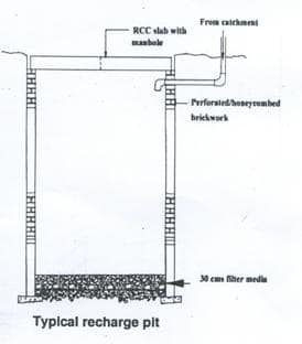
Recharge pits are small pits of any shape rectangular, square or circular, contracted with brick or stone masonry wall with weep hole at regular intervals. Top of pit can be covered with perforated covers. Bottom of pit should be filled with filter media.
The capacity of the pit can be designed on the basis of catchment area, rainfall intensity and recharge rate of soil. Usually the dimensions of the pit may be of 1 to 2 m width and 2 to 3 m deep depending on the depth of pervious strata.
These pits are suitable for recharging of shallow aquifers, and small houses. A schematic diagram of recharge pit is shown in Fig 9.

Fig 9: Recharge pit
e) Soakway or Recharge shafts
Soak away or recharge shafts are provided where upper layer of soil is alluvial or less pervious. These are bored hole of 30 cm dia. up to 10 to 15 m deep, depending on depth of pervious layer. Bore should be lined with slotted/perforated PVC/MS pipe to prevent collapse of the vertical sides.
At the top of soak away required size sump is constructed to retain runoff before the filters through soak away. Sump should be filled with filter media. A schematic diagram of recharge shaft is shown in Fig 10.


Fig 10 : Schematic Diagram of Recharge shaft
f) Recharging of dug wells
Dug well can be used as recharge structure. Rainwater from the rooftop is diverted to dug wells after passing it through filtration bed. Cleaning and desalting of dug well should be done regularly to enhance the recharge rate. The filtration method suggested for bore well recharging could be used. A schematic diagram of recharging into dug well is indicated in Fig 11 shown below.


Fig 11: Schematic diagram of recharging to dug well
g)Recharge trenches
Recharge trench in provided where upper impervious layer of soil is shallow. It is a trench excavated on the ground and refilled with porous media like pebbles, boulder or brickbats. it is usually made for harvesting the surface runoff.
Bore wells can also be provided inside the trench as recharge shafts to enhance percolation. The length of the trench is decided as per the amount of runoff expected.
Bore wells can also be provided inside the trench as recharge shafts to enhance percolation. The length of the trench is decided as per the amount of runoff expected.
This method is suitable for small houses, playgrounds, parks and roadside drains. The recharge trench can be of size 0.50 to 1.0 m wide and 1.0 to 1.5 m deep. A schematic diagram of recharging to trenches is shown in Fig below 12.


Fig 12: Recharging to trenches
h) Percolation tank
Percolation tanks are artificially created surface water bodies, submerging a land area with adequate permeability to facilitate sufficient percolation to recharge the groundwater. These can be built in big campuses where land is available and topography is suitable.
Surface runoff and roof top water can be diverted to this tank. Water accumulating in the tank percolates in the solid to augment the groundwater. The stored water can be used directly for gardening and raw use. Percolation tanks should be built in gardens, open spaces and roadside greenbelts of urban area.
No comments:
Post a Comment