Wooden Concrete Formwork Design Criteria with Calculation Formulas
Wooden formworks are generally used for construction due to its ease of use. Different criteria for design of wooden formwork and their calculation is discussed.
Formwork is substantially significant temporary construction element in the construction of structures. It provides necessary support until the concrete member achieves required strength and can support its own weight in addition to the imposed loads.
There are various materials for example steel, aluminum, fiber composite and wood from which formworks can be constructed. Manufacturers can produce steel, aluminum, and fiber composite formworks and can be utilized directly based on the information and specification provided by the manufacturer.
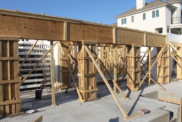
However, wood formworks as shown in Figure-1 can be made in the construction site, but is needs to be designed properly. There are different criteria that must be considered when wood formwork is designed.
In the following sections, different formwork design criteria will be discussed.

Fig.1: Wooden Formwork
Wooden Formwork Design Criteria for Concrete Construction
Following are the different criteria for design of wooden concrete formwork
- ASD adjustment factor for lumber stresses
- Factor of overall member size
- Stability factor for beam
- Column stability factor
- Factor of load duration
- Bearing area factor
- Moisture factor
- Flat application factor
- Safety factor for formwork accessories
- Repetitive factor of member utilization
- Manufactured wood products
- Adjustment factor for plywood stresses
ASD Adjustment Factor for Lumber Stresses
National design standard for wood construction 2015 recommends various adjustment factors to adjust reference design values (F) and consequently achieve permissible design values (F’) for bending stress, shear stress, bearing stress, compression stress, and elastic modulus as follows:
It should be noted that, adjustment factors in the parentheses is employed in case of truss member. Apart from those factors in the brackets, the adjustment factors will be explained in the following sections

Factor of Overall Element Size
This factor is denoted as (Cf) and it is demonstrated through tests that the size of the element, which intended to be constructed, influence the stress that causes failure. Therefore, the member size should be taken into consideration and this can be done by multiplying basic bending and compression values by size factor.
Stability Factor for Beam for Wooden Formwork Design
National design specification provided recommendation regarding the value of beam stability factor (CL). In the case where the compression edge of rectangular bending member is unstable, the stability factor for beam is calculated as per the equation provided by NDS 3.3.3.8.
Moreover, the national design specification recommends values for beam stability factor may be taken as 1 for sawn lumber based on lateral support condition and member depth to with ratio which is provided in Table-1.
Table-1: Beam Stability Factor Based on Depth to Width Ration and Lateral Support Conditions
| Depth to width ratio, b?d | Lateral Support Condition | Beam Stability Factor (CL) |
| b >= d < 2 | Lateral support is not needed | 1 |
| 4>=b/d >2 | Formwork ends should be supported by nailing, or bridging, full depth solid blocking, or other means | 1 |
| 5 >= b/d >4 | Member compression edge must be kept in position by suitable for its full length to prevent lateral displacement, and rations should be prevented at the end bearing point of the element | 1 |
| 6 >= b/d>5 | Compression edge of the member should be kept at its position by subflooring or other means, lateral displacement at end bearing point must be avoided, and at spacing of 20 cm bridging or diagonal cross bracing or full depth solid block should be provided | 1 |
| 7>=b/d >6 | Not only does the point of end bearing need to be supported to prevent rotation but also both compression edge of the member should be kept at their original position | 1 |
Column Stability Factor for Wooden Formwork Design
Column stability factor, which is denoted as (Cp) is found out as per the provisions of national design standard. The value of column stability factor is taken as 1 if lateral displacement of compression member is avoided in all direction by providing supports throughout the entire length of the member.
However, if members such as shores or braces are likely to fail in buckling instead of crushing, the column stability factor reduces the permissible compression stress that is parallel to the natural lines (grain) in the wood. The following equation is employed to compute column stability factor.

Where:
Fc*: reference compression design value parallel to natural line on wood (grain) multiply by applicable adjustment factor apart from Cp, look at section 2.3 of national design specification for wood construction
c: taken as 0.8 for sawn lumber, 0.85 for round timber poles and plies, and 0.90 for structural glued laminated timber, structural composite lumber, and cross laminated timber
FcE: is computed by applying the following expressions
Where:
le: is the effective length
le?d: is the larger of slenderness ratio about the possible buckling axis and usually do not surpass 50 apart from short loading during construction and in this case, it can be up to 75.
Factor of Load Duration for Wooden Formwork Design
It is demonstrated through tests that, the ultimate load which is carried by wood in short duration is massively greater than the maximum load that is supported by wood in normal duration. This property of wood is adjusted and arranged by applying load duration factor. Table-2 provides load duration factor for certain cumulative maximum load duration.
It is worth mentioning that, the load duration factor for most formworks is taken as 1.15, but if different parts of the formworks are reutilized for larger cumulative durations then load duration factor need to be decreased appropriately for the formwork.
Table-2: Load Duration Factor Employed for Provided Cumulative Maximum Load Duration
| Duration of loading | Load duration factor, CD |
| Load duration > 10 years | 0.9 |
| 2 months < load duration ? 10 years | 1.0 |
| 7 days < load duration ? 2 months | 1.15 |
| load duration < 7 days | 1.25 |
| Wind/ earthquake | 1.6 |
| Impact | 2.2 |
Bearing Area Factor for Wooden Formwork Design
This factor is utilized to increase concentrated load design values on wood perpendicular to grain or natural lines of wood. As per national design specification for wood construction, the bearing area factor is employed to bearings of any length at the end of the member, and to all bearing that 6 inch or more in length at any other location.
If the above conditions are reached, then the factor is computed using the following formula otherwise it is 1.
Where:
lb: is the bearing length measure parallel to wood grain.
Moisture Factor
If wood lost about thirty percent of its moisture content, its strength will increase. The essential design values have been established for a wood with moisture content of nineteen percent or smaller.
However, this moisture content might be increased because wood could expose to external conditions. In this case moisture factor need to be applied to adjust the design values.
Flat Application Factor
When 50.8cm to 101.6 cm thick wood is subjected to loading on its wide face, it will deflect around weak axis. In this situation, the stress which causes failure will be larger by small amount. Therefore, flat use factor (Cfu) is used to adjust basic design values of bending stress. Table 3 provided flat use factor.
Table-3: Flat Use Factor
| Width, mm | Thickness | |
| 50.8mm and 76.2mm | 101.6mm | |
| 50.8 and 76.2 | 1 | — |
| 101.8 | 1.1 | 1 |
| 127 | 1.1 | 1.05 |
| 152.4 | 1.15 | 1.05 |
| 203.2 | 1.15 | 1.05 |
| 254 and wider | 1.2 | 1.1 |
Safety Factor for Formwork Accessories
Hangers, anchors, and ties are examples of accessories which are employed in formwork. These accessories are commonly manufactured from steel and either ultimate or allowable strength of such tools are provided by producers.
So, if the ultimate strength is given, then it should be multiplied by safety factor to achieve permissible strength. Minimum safety factors for accessory are provided by ACI 347-04 and shown in Table 4.
Table-4: Minimum Safety Factor used for Accessory Formwork
| Accessory | Type of construction | Safety factor |
| Form tie | All applications | 2 |
| Form hangers | All applications | 2 |
| Form anchor | Formwork supporting form weight and concrete pressure only | 2 |
| Form anchor | Formwork supports form weight, concrete, construction live load, and impact | 3 |
| Anchoring inserts used as form ties | Precast concrete panel when employed as a formwork | 2 |
Repetitive Factor of Member Utilization
Bending design values is multiplied by repetitive use factor if minimum three lumbers with thickness of 5.08cm to 10.18cm are employed like plans, joists, studs, rafters, decking, or other similar members with maximum spacing of 60.96cm and connected to each other by an element that can withstand design loads.
Flooring, sheathing, subflooring are examples of members, which can withstand and distribute design load, may be used to connect lumbers. Generally, the repetitive use factor which is employed is 1.15.
Manufactured Wood Products
There are different manufactured wood products that may be used in the construction of formworks for example laminated veneer lumber (Figure 2 and Figure 3), parallel strand lumber (Figure 4 and Figure 5), laminated strand lumber (Figure 6).

Fig.2: Laminated Veneer Lumber

Fig.3: Laminated Veneer Lumber Used to Construct Formwork

Fig.4: Parallel Strand Lumber

Fig.5: Parallel Strand Lumber Used in Formwork

Fig.6: Laminated Strand Lumber
Adjustment Factor for Plywood Stresses
There are three adjustment factors namely: load duration, wet use, and experience factor which are applied to permissible stress values provided by The Engineered Wood association. The load duration factor is the same as of wood while both experience and wet use factor are considered in permissible plywood stress.
No comments:
Post a Comment