Sunday, September 9, 2018

What is Shoring? Types of Shoring and When it Used


What is Shoring? Types of Shoring and When it Used

What is Shoring?

Shoring is the construction of a temporary structure to support temporarily an unsafe structure. These support walls laterally. Shoring can be used when walls bulge out, when walls crack due to unequal settlement of foundation and repairs are to be carried out to the cracked wall, when an adjacent structure needs pulling down, when openings are to be newly made or enlarged in a wall.

Types of shoring

  1. Raking shoring
  2. Flying shoring
  3. Dead shoring

1. Raking Shoring

In this method, inclined members known as rakers are used to give lateral supports to walls (figure 1 to 3). A raking shore consists of the following components:
  1. Rakers or inclined member
  2. Wall plate
  3. Needles
  4. Cleats
  5. Bracing
  6. Sole plate
The following points are to be kept in view for the use of the raking shores:
  1. Rakers are to be inclined in the ground at 450. However the angle may be between 450and 750.
  2. For tall buildings, the length of the raker can be reduced by introducing rider raker.
  3. Rakers should be properly braced at intervals.
  4. The size of the rakers is to be decided on the basis of anticipated thrust from the wall.
  5. The centre line of a raker and the wall should meet at floor level.
  6. Shoring may be spaced at 3 to 4.5m spacing to cover longer length of the bar.
  7. The sole plate should be properly embedded into the ground on an inclination and should be of proper section and size.
  8. Wedges should not be used on sole plates since they are likely to give way under vibrations that are likely to occur.
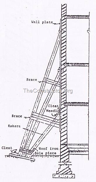
Raking Shores Wall Support
Fig.1: Raking Shores Wall Support
Detail of Raker Shores
Fig.2: Detail of Head of the Raker Shores
Raking shore for Multistoried Building
Fig.3: Raking shore for Multistoried Building where inclination of the rakers has to be limited due to short land width available

2. Flying Shoring

Flying shores is a system of providing temporary supports to the party walls of the two buildings where the intermediate building is to be pulled down and rebuilt (figure 4 and 5). All types of arrangements of supporting the unsafe structure in which the shores do not reach the ground come under this category.
The flying shore consists of wall plates, needles, cleats, horizontal struts (commonly known as horizontal shores) and inclined struts arranged in different forms which varies with the situation. In this system also the wall plates are placed against the wall and secured to it.
A horizontal strut is placed between the wall plates and is supported by a system of needle and cleats. The inclined struts are supported by the needle at their top and by straining pieces at their feet. The straining piece is also known as straining sill and is spiked to the horizontal shore. The width of straining piece is the same as that of the strut.
When the distance between the walls (to be strutted apart) is considerable, a horizontal shore can not be safe and a trussed framework of members is necessary to perform the function of flying shore.
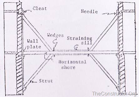
Flying Shore
Fig.4: Flying Shore
 Flying shores
Fig.5: Flying shore when the distance between two walls is considerable

3. Dead Shoring

Dead shore is the system of shoring which is used to render vertical support to walls and roofs, floors, etc when the lower part of a wall has been removed for the purpose of providing an opening in the wall or to rebuild a defective load bearing wall in a structure (figure 6 and 7).
The dead shore consists of an arrangement of beams and posts which are required to support the weight of the structure above and transfer same to the ground on firm foundation below.
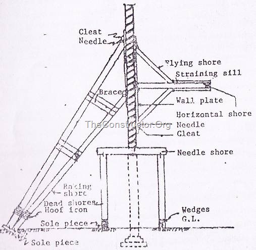
Dead Shore
Fig.6: Dead Shore
When opening in the wall are to be made, holes are cut in the wall at such a height as to allow sufficient space for insertion of the beam or girder that will be provided permanently to carry the weight of the structure above.
Distance at which the holes are cut depends upon the type of masonry and it varies from 1.2m to 1.8m centre. Beams called needles are placed in the holes and are supported by vertical props called dead shores at their ends on either side of the wall. The needles may be of timber or steel and are of sufficient section to carry the load above.
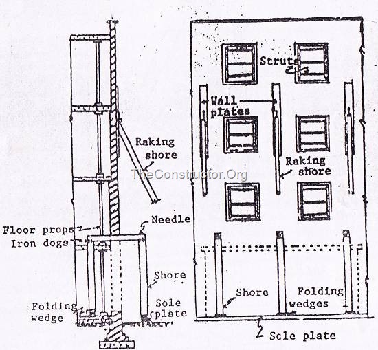
Arrangement of dead shores for making an opening in an existing wall
Fig.7: Section of the elevation showing arrangement of dead shores for making an opening in an existing wall
The dead shores stand away from wall on either side so as to allow for working space when the needle and the props are in position. The props are tightened up by folding wedges provided at their bases while the junction between the prop and the needle is secured with the help of dogs.
Before the dismantling work is started, all the doors, windows or other openings are well strutted. In order to relieve the wall of load of floors and roof above, they are independently supported.
Vibrations and shocks are bound to occur when wall cutting is done as such a measure of safety raking shores are sometimes erected before commencement of wall cutting operation.


Thursday, September 6, 2018

Determine Water Content of Soil by Oven Dry and Pycnometer Methods


Determine Water Content of Soil by Oven Dry and Pycnometer Methods

What is Water Content of Soil?

The water content of soil is is the ratio of mass of water to mass of soil which is expressed in percentage. Oven Dry Method and Pycnometer Method are commonly used to determine the water content of soil in laboratory.

1. Water Content of Soil by Oven Dry Method

The oven dry method is widely used laboratory method determine the water content or moisture content of given soil sample. It gives very accurate results.

Apparatus Required for Oven Dry Method

To determine water content by oven dry method following equipment is required.
  • Hot Air Oven
  • Non-corrodible air tight containers ( 3 no’s)
  • Digital Weight Machine (accuracy of 0.04% of mass of sample)
  • Desiccator
  • Tongs

Minimum Soil Sample Quantity

The soil sample collected from the field should be of required quantity to find the water content. The quantity of soil required is depends upon the maximum particle size and gradation of soil sample. Below table shows the soil quantity required for test based on the sieve analysis.
Table 1: Minimum Quantity of Soil Required for Water Content Determination
Size of particles more than 90% of passingMinimum Quantity ( grams)
425 micron sieve25
2 mm sieve50
4.25 mm sieve200
10 mm sieve300
20 mm sieve500
40 mm sieve1000
Wet Soil
Fig 1: Wet Soil Sample

Test Procedure of Oven Dry Method

The test procedure of Oven Dry method to find the moisture content of soil consists following steps.
  • In first step, clean and dry the containers and weigh them and note down the mass of each container (M1). Also note down the number of each container along with its weight.
  • Collect the soil sample from field. Remove the top layer of soil and collect the wet soil from bottom layers.
  • Fill the containers with required quantity of soil sample and weigh the each container and note down its mass (M2).
Oven Dry Method
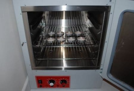
Fig 2: Placing Containers in Oven
  • Place the containers in hot air oven, arrange temperature to 110o ± 5o C and allow them to dry for 24 hours.
  • After 24 hours turn off the oven and take out the containers using tongs.
  • Cool down the containers in desiccator for one hour.
  • After that weigh containers and note down the mass (m3) of each container.

Observations and Calculations of Oven Dry Method

The data collected during the test is noted in below data sheet. From this data the water content of given soil sample is calculated by the below shown formula
Oven Dry Method Formula
Where     M1= Mass of empty container with lid,
M2= Mass of the container with wet soil and lid,
M3= Mass of the container with dry soil and lid.
Table 2: Observations and Calculations of Oven Dry Method
Sl. No.Observations and CalculationsDetermination No.
123
Observation
1Container No.
2Mass of empty container (M1)
3Mass of container + soil (M2)
4Mass of container + dry soil (M3)
Calculations
5Mass of water Mw= M2 – M3
6Mass of solids, Ms= M3 – M1
7Water content= (5)/(6)x100

Result of Oven Dry Method

Water content of the given soil sample = ______%.

2. Water Content of Soil by Pycnometer Method

Pycnometer method is also useful to determine water content. But this is used when the specific gravity of the given soil sample is already known. However, Specific gravity can also be determined using pycnometer.

Apparatus Required for Pycnometer Method

Apparatus used in pycnometer method are
  • Pycnometer
  • Weighing balance with an accuracy of 1.0g
  • Glass rod
  • Vacuum pump
Pycnometer Method
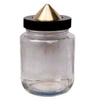
Fig 3: Pycnometer Bottle

Test Procedure of Pycnometer Method

Test procedure of pycnometer method is as follows
  • Wash, clean and dry the pycnometer and note down its mass (M1) along with brass cap and washer using weighing balance with an accuracy of 1.0 g.
  • Now place a sample of wet soil about 200 to 400 g in pycnometer and note down its mass (M2).
  • Then add water to the soil in the pycnometer to make it about half full.
  • Stir the soil using glass rod to remove air voids of the soil sample. If available connect the vacuum pump to the soil specimen to remove entrapped air.
  • Add some more water and after eliminating the entrapped air stop stirring and fix the brass cap. More water is added through hole in brass cap until the water is flush with the hole.
  • Now take the mass of pycnometer (M3).
  • Now empty and wash the pycnometer. Then fill it with only water and take its mass (M4).

Observations and Calculations of Pycnometer Method

The water content (w) of the soil sample using pycnometer method is calculated from the below formula
Pycnometer Method Formula
Where   M1=mass of empty Pycnometer,
M2= mass of the Pycnometer with wet soil
M3= mass of the Pycnometer and soil, filled with water,
M4 = mass of Pycnometer filled with water only.
G= Specific gravity of solids.
Table 2: Observations and Calculations of Pycnometer Method
Sl. No.Observations and CalculationsDetermination No.
123
Observation
1Mass of empty pycnometer (M1)
2Mass of pycnometer + wet soil (M2)
3Mass of Pycnometer soil filled with water (M3)
4Mass of Pycnometer filled with water only (M4)
Calculations
5M2 – M1
6M3 – M4
7(G – 1) / G
8w (using above formula)

Result of Pycnometer Method

Water content of the given soil sample = _______%.

What is Soil Texture? Classification System of Soil Texture


What is Soil Texture? Classification System of Soil Texture

What is Soil Texture?

The texture of the soil is an indication of the relative content of particles of various sizes in the soil. It will indicate the percentage of sand, silt, and clay present in the soil. Soil texture will influence the ease with which the soil can be worked. The texture of the soil is dependent on:
  • Particle size distribution
  • The shape of the particles
  • Gradation of the particles
When the textural classification of soil is concerned, we only take into consideration the particle size distribution. The other two parameters are difficult to incorporate in this classification.

Textural Classification System

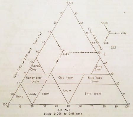
The US Bureau of Public Roads recommends triangular classification system for soil which is commonly called as the textural classification system. The figure- 1 below shows the textural classification system, where the three sides of the equilateral triangle represent the percentage of sand, silt and clay. Where the size of,
  • Sand = 0.05 – 2mm
  • Silt = 0.005 – 0.05mm
  • Clay = size < 0.005mm
Textural classification system
Fig.1: The Textural classification system
As shown above, the equilateral triangle has 10 zones. Each zone of the triangle will represent each type of soil. Hence, by determining the zone the type of soil can be classified. In order to locate the point a key is given. This key will give an indication about the direction at which the lines are to be drawn so that points can be located.
For example, as shown in the figure- 1, “P” is located corresponding to 30% sand, 50% clay and 20% slit. Now the point P will fall on the zone clay. Hence the soil is classified as clay.
Soils containing different constituents can be easily classified by the textural classification system. This classification system ensures no particles greater than 2mm size is present. In cases where a certain amount of particles greater than 2mm is present a correction is required. Here the percentage of sand, silt and clay is increased to 100%.
For example, if the soil sample contains 20% of particles that are greater than 2mm size, actual sum of sand silt and clay (%) = 80.If percentage of sand = 12, percentage of silt = 24, percentage of clay = 44. The Correction factor will be (100/80). Therefore, the corrected % would be 15, 30 and 55% respectively.
The term “loam” is encountered while working with the textural classification system. Loam is used to describe a mixture of sand, silt, and clay in various proportions. The term loam is not used in soil engineering and a modified triangular diagram was proposed by Mississippi river commission USA (Figure – 2).
Modified triangle diagram
Fig. 2: Modified triangle diagram

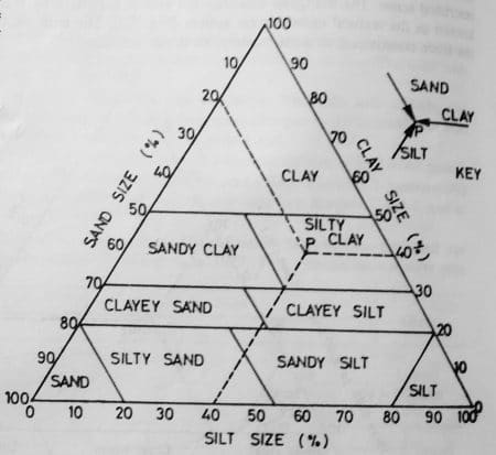
Right triangle chart

In Right triangle chart, the two perpendicular sides will represent clay and silt percentage. As some of the percentages of sand, silt and clay will be 100%, It is not necessary to plot all the three. If clay and silt is represented in the right triangle
The percentage of sand particles = 100% – (sum of percentages of silt and clay).
Right triangle chart
Fig. 3: Right triangle chart
From figure – 3, the lines of intersection of silt and clay will give the textural classification. The right triangle diagram is more convenient than a triangular diagram. The right triangle diagram consists of orthogonal lines which make the point location easy.

What is Crazing in Concrete? Causes and Prevention of Crazing


What is Crazing in Concrete? Causes and Prevention of Crazing

What is Crazing in Concrete?

Crazing in concrete is the development of a network of fine random cracks or fissures on the surface of concrete caused by shrinkage of the surface layer. These cracks are rarely more than 3mm deep, and are more noticeable on over floated or steel-troweled surfaces.
The irregular hexagonal areas enclosed by the cracks are typically no more than 40mm wide and may be as small as 10mm in unusual instances (Fig. 1(a) & (b)).
Crazing in Concrete
Generally, craze cracks develop at an early age and are apparent the day after placement or at least by the end of the first weak. Often they are not readily visible until the surface has been wetted and it is beginning to dry.
They do not affect the structural integrity of concrete and rarely do they affect durability. However crazed surfaces can be unsightly.
Crazing in Concrete

Causes of Crazing in Concrete

Crazing in concrete usually occurs because of wrong construction practices like:
  • Poor or inadequate curing – Curing of concrete is required to maintain the moisture content when concrete starts to set and gain strength. When the evaporation rate from the concrete surface is higher than the moisture gain from curing, the crazing cracks occurs in concrete. This occurs due to direct sunlight, low humidity, or drying winds.
  • Intermittent wet curing and drying – intermittent curing allows the concrete surface to dry for sometime and this leads to concrete crazing.
  • Excessive floating is the accumulation of cement paste on the top of concrete while the coarse aggregate settles down. This causes the moisture accumulation at top which when dries up causes crazing.
  • Excessive laitance on surface.
  • Finishing with float when bleed water is on the surface.
  • Sprinkling cement on the surface to dry up the bleed water. This will create a weak surface on the concrete due to concentration of fines on surface.
  • Over vibration loading extra bleed & laitance on surface.

Preventive Measures for Crazing in Concrete

  • Proper and early start of curing prevents the loss of moisture in concrete and helps in hydration process of concrete. The maintenance of continuous supply of moisture in concrete prevent the appearance of crazing on concrete surface.
  • Use of curing compound on the surface prevents the rapid evaporation of moisture from concrete surface and crazing is prevented.
  • Never sprinkle dry cement or a mixture of cement and fine sand on the surface of the plastic concrete to prevent the appearance of crazing.
  • Use low water-cement ratio as possible, consistent with adequate compaction.
  • Use workability enhancing air-entrained concrete with a moderate slump. Air-entrainment reduces rate of bleeding in fresh concrete and reduces the likelihood of crazing.
  • Use low slump concrete, Higher slump allows the concrete mixture to segregate, resulting in a weak surface layer.
  • Avoid steep moisture difference between concrete surface and the interior of the concrete.
  • Trowel the surface as little as possible and in particular avoid the use of steel float.
  • Avoid the use of rich finishing mixes, not richer than 1:3.
  • Avoid over vibration which results in bringing too much slurry to the top or side.
  • Avoid grouting processes or rubbing the surface with neat cement paste.