Tuesday, October 30, 2018

Preparation of Bar Bending Schedule and Its Advantages

Preparation of Bar Bending Schedule

Bar bending schedule (or schedule of bars) is a list of reinforcement bars for a given reinforced concrete work item, and is presented in a tabular form for easy visual reference.
Table of bar bending schedule summarizes all the needed particulars of bars – diameter, shape of bending, length of each bent and straight portions, angles of bending, total length of each bar, and number of each type of bar. This information is a great help in preparing an estimate of quantities.

Calculation of Reinforcement Shape, Cutting and Bending Lengths

Figure 1 depicts the shape and proportions ofhooks and bends in the reinforcement bars – these are standard proportions that are adhered to:
(a) Length of one hook = (4d ) + [(4d+ d )] – where, (4d+ d ) refers to the curved portion = 9d.
(b) The additional length (la) that is introduced in the simple, straight end-to-end length of a reinforcement bar due to being bent up at  say 30o to 60o, but it is generally 45o) = l1 – l2 = la
Where,
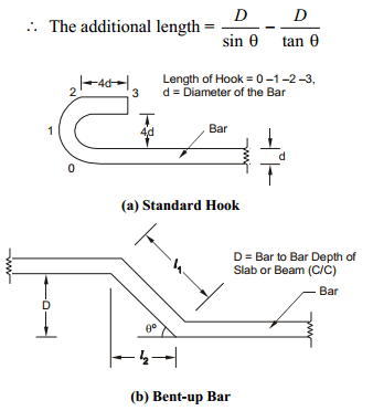
Hooks and bends in reinforcement
Fig: Hooks and bends in Reinforcement
Giving different values to clip_image005respectively), we get different values of la, as tabulated below:
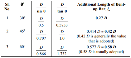
length of bent up bars
Figure 2 presents the procedure to arrive at the length of hooks and the total length of a given steel reinforcement.
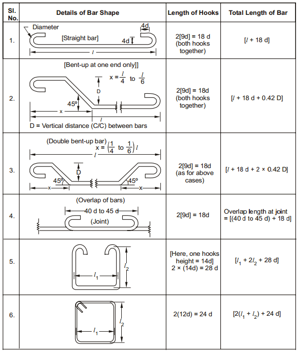
Typical Bar Bending Schedule
Fig: Typical Bar Bending Schedule

Advantages of Bar Bending Schedule

Bar bending schedule provides details of reinforcement cutting and bending length. Advantages of bar bending schedule is when used along with reinforcement detailed drawing improves the quality of construction, cost and time saving for concrete construction works.
Advantages of bar bending schedule in concrete construction are:
1. When Bar bending schedule is available, cutting and bending of reinforcement can be done at factory and transported to site. This increases faster execution at site and reduces construction time and cost due to less requirement of workers for bar bending. Bar bending also avoids the wastage of steel reinforcement (5 to 10%) and thus saves project cost.
2. Using bar bending schedule for when used for Fe500, it saves 10% more steel reinforcement compared to fe415.
3. It improves the quality control at site as reinforcement is provided as per bar bending schedule which is prepared using the provisions of respective detailing standard codes.
4. It provides the better estimation of reinforcement steel requirement for each and every structural member which can be used to compute overall reinforcement requirement for entire project.
5. It provides better stock management for reinforcement. Steel requirement for next phase of construction can be estimated with accuracy and procurement can be done. This prevents stocking of extra steel reinforcement at site for longer time, preventing corrosion of reinforcement in case of coastal areas. It also prevents shortage of reinforcement for ongoing work by accurate estimation and thus concrete construction works can proceed smoothly.
6. Bar bending schedule is very much useful during auditing of reinforcement and provides checks on theft and pilferage.
7. Bar bending schedule can be used for reinforcement cutting, bending and making skeleton of structural member before it can be placed at the required position. Other activities such as excavation, PCC etc can proceed parallel with this activity. So, overall project activity management becomes easy and reduces time of construction. It becomes helpful in preventing any damages due to construction time overrun.
8. It provides benchmarks for quantity and quality requirements for reinforcement and concrete works.
9. Bar bending schedule provides the steel quantity requirement much accurately and thus provides an option to optimize the design in case of cost overrun.
10. It becomes easy for site engineers to verify and approve the bar bending and cutting length during inspection before placement of concrete with the use of bar bending schedule and helps in better quality control.
11. It enables easy and fast preparation of bills of construction works for clients and contractors.
12. The quantity of reinforcement to be used is calculated using engineering formulas and standard codes, so there is no option for approximate estimation of steel reinforcement.
13. With the use of bar bending schedule, mechanization of cutting and bending of reinforcement can be done, again reducing the cost and time of project and dependency on skilled labor requirement. It also improves the reliability on accuracy of bar cutting and bending.
14. When mechanized bar cutting and bending is used, the cost of reinforced concrete work per unit reduces and helps in cost optimization of construction project.

Typical Construction Joints Details and Location for Beams and Columns


Construction joints in RCC beams and columns are required when the concreting has to be stopped for the day or more than 30 minutes. In such case, typical construction joints shall be provided so that bond is maintained between set concrete and fresh concrete.
Below are some images showing correct method of construction joints to be provided in columns, beams and beam-column junction. To know about what is construction joint.

1. Construction Joints in Column

Following figure shows correct method of providing construction joint in column. Construction joint in column shall not be provided with smooth surface or inclined surface. The top surface of the column should be rough with parts of coarse aggregates being seen.
Fig: Typical Construction Joint in RCC Column

2. Construction Joints in Beams and Beam-Column Joint:

Following figure shows the typical construction joint to be provided in beams and beam column joints.
Fig: Typical Construction Joint in Beams and Beam-Column Joint
The arrow symbol shows the direction of concreting, tick mark shows the correct method of providing construction joint while cross-mark shows the wrong method.
From the figure it can be seen that construction joint in the beams should be provided at 1/4 the span of beam from the face of the column and should not be provided on the column.
For a beam column joint, the construction joint for the column should be provided after construction of some length of column above beam level, and for the beam, it should be provided at a span of 1/4th from the face of the column.

Monday, October 29, 2018

Minimum Height and Size Standards for Rooms in Buildings


Minimum heights and size standards for rooms ensures that there is good ventilation, lights and comfortable living inside the room. Height and size standards for rooms varies from one country to another and is mostly based on the preference of clients to meet their demand.
However, in the absence of controls, developers (both public and private sector) tend to reduce the size of dwellings being developed whilst trying to avoid any reduction in value. Added to that, established minimum height and size standards allows disciplined and systematic growth of buildings and towns, and provide proper utilization of space.

Height Regulation for Rooms

1. Habitable Rooms

  • The minimum height from the surface of the floor to the ceiling or bottom of slab should be not less than 2.75m.
  • For air-conditioned rooms, a height of not less than 2.4 m measured from the top of the floor to the lowest point of the air-conditioning duct or the false ceiling should be provided.
  • According to Ontario Building Code (OBC), 2.3 m over at least 75% of the required floor area with a clear height of at least 2.1 m at any point over the required area

2. Bedroom Height Restrictions

  • As per OBC, the bedroom height should be 2.3 m over at least 50% of the required floor area.
  • Alternatively, 2.1 m over 100% of the required floor area
  • Any part of the floor area having a height of less than 1.4 m shall not count when calculating required floor area

3. Bathrooms, water closets and stores

  • The height of all such rooms measured from the floor in the ceiling should not be less than 2.4m.
  • In the case of a passage under the landing, the minimum headway may be kept as 2.2m.
  • According to OBC, bathroom minimum height of 2.1 m in any area where a person would be in a standing position

4. Kitchen

  • The height of the kitchen measured from the floor to the lowest point in the ceiling should not be less than 2.75m except for the portion to accommodate floor trap of the floor.
  • However, according to OBC, kitchen height should be 2.3 m over at least 75% of the required floor area with a clear height of at least 2.1 m at any point over the required area.

5. Ledge

It shall have a minimum head room of 2.2m.

6. Hallways

Minimum height should be 2.1 m
Fig.1: Height of Rooms

Minimum Standard Sizes of Rooms

1. Habitable Rooms

  • The area of habitable rooms should not be less than 9.5m2 where there is only one room. However, such rooms shall have at least 13.5mof floor area and no dimension less than 3.0 m as per Ontario Building Code (OBC).
  • Where there are two rooms, one of these should not be less than 9.5 mand other be not less than 7.5 m2 with a minimum width of 2.4m.
  • Natural ventilation shall be provided.

2. Dining room

  • It should have a floor area not less than 9.5m2 with a minimum width of 2.4m.
  • According to OBC, dining room shall have at least 3.25 m2 of floor space when combined with other rooms, and at least 7.0mof area when not combined.
  • minimum dimension of 2.3 m.
  • Dining rooms vary greatly in size. It should be ensured that furniture is accommodated.
  • Natural ventilation shall be provided.
    Fig. 2: Dining Room

3. Primary Bedrooms

  • One bedroom shall have at least 9.8m2of floor area
  • Minimum dimension should be 2.7 m
  • Natural ventilation must be provided

4. Secondary Bedrooms

  • It shall have at least 7m2 of floor area
  • Minimum dimension is 2.0 m

5. Kitchen

  • Minimum floor area required is not less than 5.5 m2. But OBC specify that kitchen room shall have at least 4.2m2 of floor area
  • It should not be less than 1.8min width at any part. With a separate storeroom, the area may be reduced to 4.5m2.
  • Mechanical ventilation must be provided (exhaust fan).
  • Ensure that appliances can all open without interfering with one another, and that standing space is provided.
    Fig. 3: Mechanical appliances in kitchen room

6. Bathrooms and water closets

  1. The size of bathroom should not be less than 1.5m x 1.2m or 1.8 m2.
  2. If it is combined with water closet, its floor area should not be less than 2.8 m2.
  3. the minimum floor area of a water closet should be 1.1 m2.

7. Ledge

  1. A ledge in a habitable room shall not cover more than 25% of the floor area of the floor on which it is constructed
  2. It should not interfere with the ventilation of the room under any circumstances.

8. Hallways

Hallways shall have a width of at least 860 mm except where the overall width of the building is less than 4.3 m, and this may be reduced to 710 mm

9. Mezzanine floor

The minimum size of a mezzanine floor, if it is used as a living room, should not be less than 9.5m2.