Thursday, July 26, 2018

Theodolite Parts and its Functions for Angle Measurements in Surveying


Theodolite Parts and its Functions for Angle Measurements in Surveying

Theodolite has many parts which needs to be adjusted every time while surveying. It is important to know about theodolite parts and their functions before using it to minimize errors during theodolite surveying.
Theodolite is an instrument used in surveying to measure horizontal and vertical angles. It is also used for leveling, indirect measure of distances and prolonging a line etc. The line of sight of theodolite can be rotated through 180oin vertical plane about its horizontal axis.

Parts of Theodolite and their Functions

Following are the parts of a theodolite:
  • Telescope
  • Vertical circle
  • Index frame
  • The standards
  • The upper plate
  • The lower plate
  • The leveling head
  • The shifting head
  • Plate level
  • Tripod
  • Plumb bob
  • Magnetic compass
Theodolite Parts and Functions

Telescope

A telescope is a focusing instrument which has object piece at one end and eye piece at the other end. It rotates about horizontal axis in vertical plane. The graduations are up to an accuracy of 20’.

Vertical Circle

Vertical circle is fitted to telescope and moves simultaneously with telescope. It has graduation in each quadrant numbered from 0 to 90degrees.

Index Frame

It is also called as t-frame or vernier frame. It consists two arms vertical and horizontal. Vertical arm helps to lock the telescope at desired level and horizontal arm is useful to take the measurements of vertical angles.

The Standards

The standards are the frames which supports telescope and allow it to rotate about vertical axis. Generally, these are in letter A-shape. So, standards are also called as A-frame.

The Upper Plate

This is also called as vernier plate. The top surface of upper plate gives support to the standards. It also consists an upper clamping screw with respect to tangents screw which helps to fixing it to the lower plate.
When the upper clamping screw is tightened both upper and lower plates are attached and moved together with some relative motion because of upper tangent screw. The upper [late also consists two verniers with magnifiers which are arranged diagonally. It is attached tow inner spindle.

The Lower Plate

This is also called as scale plate. Because it contains a scale on which 0 to 360 readings are graduated. It is attached to the outer spindle and consists lower clamping screw. If lower clamp screw is loosened and upper clamp screw is tightened, both plates can rotate together.
Similarly, if lower clamping screw is tightened and upper clamp is loosened then, only upper plate is movable and lower plate is fixed with tribratch plate.

The Leveling Head

The leveling head contains two parallel triangular plates called as tribratch plates. The upper one is known as upper tribratch plate and is used to level the upper plate and telescope with the help of leveling screws provided at its three ends. The lower one is called as lower tribratch plate and is attached to the tripod stand.

The Shifting Head

Shifting head also contains two parallel plates which are moved one over the other with in small area. Shifting head lies below the lower plate. It is useful to centering the whole instrument over the station.

Plate Level

Plate levels are carried by the upper plate which are right angles to each other with one of them is parallel to trunnion axis. These plate levels help the telescope to settle in exact vertical position.

Tripod

Tripod is nothing but a stand on which theodolite is mounted. It should place in such a way that theodolite should be in exact leveled position. The tripod has legs with steel shoes at their ends. These hold the ground strongly without any movement when placed.
Tripod has an external screw which helps to attach the theodolite by tribratch plate in fixed position.

Plumb Bob

Plumb bob is tool having a cone shaped weight attached to a long thread. The weight is hanged using thread from the center of tripod stand and centering of theodolite is done.

Magnetic Compass

Simpler theodolites may contain circular compass box in the center of upper plate. When we select north as reference meridian it will be useful.
Equipment Used for Measuring Angles and Elevations in Surveying


Equipment Used for Measuring Angles and Elevations in Surveying

There are various surveying instruments for measurement of angles and elevations. Types, properties, uses and details of these surveying equipment is discussed.
Among the variety of instruments that are available to measure angles and elevations, it is important to choose the best one that is more suitable for the specific job.
The best source of information for a specific instrument is the reference of owner’s manual or the product catalog that is provided by the manufacturer.

Equipment Used for Measuring Angles and Elevations in Surveying

The common equipment used for measuring angles and elevations in surveying are:
  • Hand level
  • Abney level
  • Dumpy level
  • Automatic level
  • Laser level
  • Transit
  • Theodolite

Hand Levels for Measurement of Elevation and Slope in Surveying

As the name tells, these are levels that are held in the hands of the operator. Hand levels are the simplest level among the surveying instruments. The hand level employs a spirit level and a single cross-hair.
The main purpose of hand level is to ensure that the chains are in level when the horizontal distance is measured with the help of plumb bobs. It is also used for the same purpose for slope estimation and change in elevation.
The common magnification of hand level is from zero to 5x. Hand levels with more sophisticated mechanism will have stadia hairs to measure the horizontal distance.
Hand Levels for Measurement of Elevation and Slope in Surveying
Fig.1: A hand Level in Surveying
The hand level is primarily used to estimate the elevation and the slope. The slope is defined as the rate of change of elevation. To measure the slope with the hand level, it is essential to stand at the bottom of the slope and hold the hand level in a horizontal position.
Now the point where the line of sight strikes the ground is marked. With the help of the distance to this point and the height of user’s eye from the ground, the slope is determined.
% slope = (Rise/Run) x 100
The eye height of the user is the rise.
The distance from the observation point to where the line of sight strikes the ground is the run.
The distance can be measured by pacing. The result is found to have low precision, because of the low precision of measuring distance by pacing and the measured distance is the sloped distance (not horizontal distance).

Abney Level for Measurement of Angles and Slope in Surveying

Hand levels with more sophistication will form Abney levels. This comprise of a direct reading scale for vertical angles and slope, stadia hairs and better optics and magnification.
Compared to hand level, the precision of slope calculation is better. The measuring distance of the stadia of the Abney level has a precision of 1/10 of a foot. The distance measured using stadia is horizontal.
Most of the Abney levels have provision for adjustment for both focusing as well as magnification. For preliminary surveying, they give appreciable accuracy if a rod and target are employed.
Abney Level for Measurement of Angles and Slope in Surveying
Fig.2: Abney Level in Surveying
Using a stick or rod of known height with the hand level and the Abney level helps to improve the accuracy of measurement. The use of stick also helps in keeping the level steady.

Dumpy Level for Measurement of Angles and Elevation in Surveying

The dumpy level is the simplest form of the level that is supported by a tripod. The accuracy of the instrument is increased by the use of a tripod. The tripod also helps in providing a reference for the horizontal angles.
A dumpy level comprises a telescope and a spirit level that is mounted parallel to the line of sight of the telescope.
The telescope in the dumpy level will have at least one horizontal cross hair that is mounted in line with the line of sight. It also has a vertical cross hair and two stadia cross hairs.
Dumpy Level for Measurement of Angles and Elevation in Surveying
Fig.3: Dumpy Level in Surveying
A mechanism called the leveling plate rotates in 360 degrees. This is the platforms onto which the telescope and the spirit level are mounted. The whole mechanism is placed on a plate that is attached to a tripod. This is later leveled to start the surveying.

Automatic Level for Measurement of Angles and Elevation

The automatic level is designed such a way to automatically compensate for small movements in the instrument and keep the line of sight in level. An internal compensator completes the leveling process once the instrument is nearly level. Later it maintains the line of sight in the horizontal position throughout needed.
Automatic Level for Measurement of Angles and Elevation
Fig.4: Automatic Level
The internal compensator does not let the instrument to be knocked out of level by any slight bumps. The movements caused by the wind are also compensated by the internal compensators.
The instrument is leveled with three leveling screws instead of four. The automatic levels make use of bull’s eye spirit level compared to the tube level. The combination of three leveling screws and the bull’s eye spirit level helps in faster set up.
A variety of models is available for automatic levels. Some are more accurate and more precise when compared to the dumpy levels. These are less accurate compared with transits and the total stations.

Laser Level for Measurement of Angles and Elevation

The laser level is a measuring level that makes use of a beam of laser light to establish the line of sight i.e. the reference line. The different types that come under this category are:
  • Single beam invisible
  • Single beam visible
  • Circular beam visible
  • Circular beam invisible
The circular beam lasers can be classified into rotating and nonrotating. The single beam laser will make use a single dot or a short line. The circular beam laser will produce a 360-degree beam.
Laser Level for Measurement of Angles and Elevation
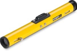
Fig.5: Laser Level
The distinct advantage of laser levels is they can be operated by a single person. The laser level is mounted on a tripod and later leveled. Once the system is turned on, it does not need any supervision further. After which the surveyor can record the rod readings by walking around the area anywhere within the range of the beam.
This system also has the advantage of multiple detectors which can be used with a single laser. This will thus enable to record data simultaneously by more than one person.

Transit Level for Measurement of Angles and Elevation

A transit level is an optical instrument or a telescope that comprises a built-in spirit level that is mounted on the spirit level. They are used to determine the relative position of lines and objects mainly for surveying and building. The transit levels are very precise. The transit level helps in establishing the reference line.
Transit Level for Measurement of Angles and Elevation
Fig.6: Transit Level

Theodolite for Measurement of Angles in Surveying

A theodolite is a precision instrument that is used to measure the angle in the horizontal and vertical planes. Theodolite is most commonly used in surveying. But they are also used in the areas of metrology and rocket launch technology.
A modern developed theodolite consists of a movable telescope that is mounted within two perpendicular axes called the horizontal or the trunnion axis and the vertical axis. Pointing the telescope on a target object will enable measurement of angle with great precision.
The theodolite with the help of a forced centering plate is mounted on the tripod head. The forced centering plate or the tribrach consist of four thumbscrews, in the case of initial theodolites and three or four rapid leveling in the case of modern theodolites.
Transit Level for Measurement of Angles and Elevation
Fig.7: Theodolite in Surveying
The theodolite must be placed vertically above the point to be measured with the help of a plumb bob or an optical plummet or any laser plummet. After this, the level is set for the instrument using the leveling foot screws and tubular spirit bubbles.

Total Station in Surveying – Operation, Uses and Advantages


Total Station in Surveying – Operation, Uses and Advantages

What is a Total Station?

Total station is a surveying equipment combination of Electromagnetic distance measuring equipment and electronic theodolite. It is also integrated with microprocessor, electronic data collector and storage system. The instrument can be used to measure horizontal and vertical angles as well as sloping distance of object to the instrument.

Capability of a Total Station

Microprocessor unit in total station processes the data collected to compute:
  1. Average of multiple angles measured.
  2. Average of multiple distance measured.
  3. Horizontal distance.
  4. Distance between any two points.
  5. Elevation of objects and
  6. All the three coordinates of the observed points.
Data collected and processed in a Total Station can be downloaded to computers for further processing.
Total station is a compact instrument and weighs 50 to 55 N. A person can easily carry it to the field. Total stations with different accuracy, in angle measurement and different range of measurements are available in the market. Figure below shows one such instrument manufactured by SOKKIA Co. Ltd. Tokyo, Japan.
Parts of total station
Fig: Parts of total station

Important Operations of Total Station

Distance Measurement

Electronic distance measuring (EDM) instrument is a major part of total station. Its range varies from 2.8 km to 4.2 km. The accuracy of measurement varies from 5 mm to 10 mm per km measurement. They are used with automatic target recognizer. The distance measured is always sloping distance from instrument to the object.

Angle Measurements

The electronic theodolite part of total station is used for measuring vertical and horizontal angle. For measurement of horizontal angles any convenient direction may be taken as reference direction. For vertical angle measurement vertical upward (zenith) direction is taken as reference direction. The accuracy of angle measurement varies from 2 to 6 seconds.

Data Processing

This instrument is provided with an inbuilt microprocessor. The microprocessor averages multiple observations. With the help of slope distance and vertical and horizontal angles measured, when height of axis of instrument and targets are supplied, the microprocessor computes the horizontal distance and X, Y, Z coordinates.
The processor is capable of applying temperature and pressure corrections to the measurements, if atmospheric temperature and pressures are supplied.

Display

Electronic display unit is capable of displaying various values when respective keys are pressed. The system is capable of displaying horizontal distance, vertical distance, horizontal and vertical angles, difference in elevations of two observed points and all the three coordinates of the observed points.

Electronic Book

Each point data can be stored in an electronic note book (like compact disc). The capacity of electronic note book varies from 2000 points to 4000 points data. Surveyor can unload the data stored in note book to computer and reuse the note book.

Uses of Total Station

The total station instrument is mounted on a tripod and is levelled by operating levelling screws. Within a small range instrument is capable of adjusting itself to the level position. Then vertical and horizontal reference directions are indexed using onboard keys.
It is possible to set required units for distance, temperature and pressure (FPS or SI). Surveyor can select measurement mode like fine, coarse, single or repeated.
When target is sighted, horizontal and vertical angles as well as sloping distances are measured and by pressing appropriate keys they are recorded along with point number. Heights of instrument and targets can be keyed in after measuring them with tapes. Then processor computes various information about the point and displays on screen.
This information is also stored in the electronic notebook. At the end of the day or whenever electronic note book is full, the information stored is downloaded to computers.
The point data downloaded to the computer can be used for further processing. There are software like auto civil and auto plotter clubbed with AutoCad which can be used for plotting contours at any specified interval and for plotting cross-section along any specified line.

Advantages of Using Total Stations

The following are some of the major advantages of using total station over the conventional surveying instruments:
  1. Field work is carried out very fast.
  2. Accuracy of measurement is high.
  3. Manual errors involved in reading and recording are eliminated.
  4. Calculation of coordinates is very fast and accurate. Even corrections for temperature and pressure are automatically made.
  5. Computers can be employed for map making and plotting contour and cross-sections. Contour intervals and scales can be changed in no time.
However, surveyor  should check the working condition of the instruments before using. For this standard points may be located near survey office and before taking out instrument for field work, its working is checked by observing those standard points from the specified instrument station.

Dumpy Level Surveying – Components, Procedure, Advantages


Dumpy Level Surveying – Components, Procedure, Advantages

What is Dumpy Level?

Dumpy level is commonly used leveling instrument to locate the points in same horizontal plane. It is also called as automatic level or builder’s level. Elevations of different points and distance between the points of same elevation can be determined by dumpy level.
The telescope is fixed to its supports in dumpy level and hence it cannot be rotated in vertical axis. It is invented by William Gravatt in 1832.
Dumpy Level Surveying

Components of Dumpy Level

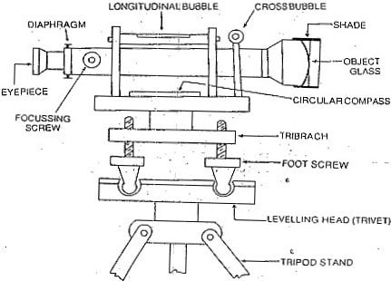
Dumpy level consists the following parts or components
  • Telescope
  • Bubble tubes
  • Compass
  • Vertical spindle
  • Tribrach screws
  • Foot screws
  • Leveling head
  • Tripod
Components of a Dumpy Level
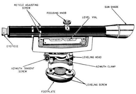
Fig: Components of a Dumpy Level

Telescope

Telescope is used to observe the distant object through line of sight provided by its arrangement. In general, the telescope is fixed to the vertical spindle of dumpy level so that it can be rotated along with vertical spindle.

Parts of Telescope in Dumpy Level

The important parts of telescope are as follows
  • Eye piece
  • Objective lens
  • Diaphragm
  • Focusing screw
  • Ray shade
Eye piece
Eye piece is used by the observer’s eye to view the distant object. It contains magnifying glass which magnify the observing image and also the cross hairs of diaphragm. So, accurate reading can be obtained. Erecting eyepiece is used to view the normal image which is generally inverted by objective lens.
Objective lens
Objective lens are provided at the other end of the telescope. The objective lens consists of two parts, the front part consists convex type lens and the back part consists concave lens. So, the image obtained from the objective lens is always inverted.
Diaphragm
Diaphragm is provided in front of the eye piece. It contains cross hairs made of dark metal which are arranged in perfect perpendicular positions. These cross hairs are used by the eye piece to bisect the objective through objective lens.
Diaphragm in Dumpy Level
Focusing screw
Focusing screw is used to adjust the focus if cross hairs and the image clarity. The magnification of eye piece is managed by this focusing screw.
Ray shade
Ray shade is used to prevent the objective lens from sunlight or any other light rays which may cause disturbance to the line of sight.

Bubble tubes

Bubble tubes are provided to check the level of the instrument. Two bubble tubes are provided in a dumpy level which are arranged perpendicular to each other on the top of the telescope. One tube is called as longitudinal bubble tube and another is called as cross bubble tube. The instrument is said to be in perfect position when both the bubbles of the tubes are at center or middle of the tube.

Compass

Compass is used to determine the magnetic bearing of line. In case of dumpy level, circular compass is provided just under the telescope. The compass contains a pointer in it and readings are marked inside it. The pointer is set to zero when it faces the north line from which the magnetic bearings are measured.

Vertical spindle

Vertical spindle is located at the center of the whole instrument. The telescope can be rotated in horizontal direction with respect to vertical spindle. The instrument is connected to the tripod stand using vertical spindle.

Tribrach

Tribrach plate is parallel to the leveling head or trivet. It is connected to trivet by leveling screws or foot screws which can adjust the tribrach plate. The horizontal level of the instrument can be achieved by adjusting this tribrach plate.
Tribrach of Dumpy Level

Foot screws

Foot screws are provided to regulate the tribrach position and hence the instrument can be leveled which is known by observing the bubble tube. The tribrach plates can be lowered or raised using foot screws. The position of tribrach is said to be correct when the bubble in bubble tube is at center.

Leveling head

Leveling head is also called as trivet. It contains two triangular shaped plates which are arranged parallel to each other. Three groves are provided at the three corners of the plates in which foot screws are supported.

Tripod

Tripod is used to support the whole leveling instrument on its top. It consists three legs which can be adjustable to required position. The legs are of same height and they may be solid or hollow. Steel shoes are provided at the bottom of each leg to hold the ground in a fixed position.
Tripod of Dumpy Level

Procedure of Dumpy Level Surveying

The procedure of dumpy level surveying starts with some temporary adjustments which are:
  • Setting up of instrument
  • Leveling up
  • Focusing

Setting up of Dumpy Level

The instrument is fixed to the tripod stand using clamp screws. Spread the tripod legs and position the instrument at convenient height. Firstly fix the two legs in the ground at a point and centering of bubble in the bubble tubes is done by adjusting third leg.

Leveling up

The leveling up of an instrument is done using foot screws or leveling screws. In this case, the telescope is arranged parallel to the any two leveling screws and the bubble in the tube is centered by turning both the screws either inwards or outwards.
When it is centered, then the telescope is turned 90o and the third screw is turned until the bubble come to center. Repeat the process until the bubble in the tube always stays at the middle in any position of telescope.

Focusing

Focusing is done by adjusting eye piece and focusing screw. Eye piece is adjusted until the cross hairs of diaphragm are clearly visible. To eliminate the parallax error, a white paper is used to obtain sharp vision of cross hairs.
Focusing screw is adjusted to view the clear image of the objective or staff. Focusing is said to be done when the cross hairs bisect the objective or staff with clear vision.
After completion the above temporary adjustments, now it’s time to take levels of required positions or points. The telescope is rotated towards the line of objective or staff and bisect it. The levels are noted at different points which values are decided from a known bench mark point in that area. The details are tabulated as below.
Position observedLevel readingHCR (higher cross hair reading)LCR (lower cross hair reading)(HCR-LCR) x 100Distance of point from instrumentRemarks / Error
1
2
3

Benefits of Dumpy Level Surveying

  • Dumpy level is easy to use.
  • Adjustments can be made as per the requirement on any type of ground.
  • Level readings are very accurate in case of dumpy level.
  • Optical power is high for dumpy level.
  • Price of dumpy level is cheap when compared to other instruments.

Drawbacks of Dumpy Level Surveying

  • It is limited to only horizontal angle measurement.
  • The angles obtained by dumpy are not that accurate.