Monday, September 24, 2018

Sandblasting Concrete Surface- Process and Advantages


Sandblasting Concrete Surface- Process and Advantages


Sandblasting is a method to texture the surface of hardened concrete on patio, walls, columns, driveways, floors to remove paint or expose aggregates. The extent of sand blasting ranges from light cleaning to a deep cutting operation that exposes aggregates to around 2 cm.

Concrete Sandblasting Equipment

The equipment required for blasting might change based on the specified cut depth. If only the surface is needed to be lightly removed, then any sandblasting tool or equipment can execute the work properly.
Lightly blasted concrete
Fig. 1: Lightly blasted concrete
However, if the designated texture required a fairly deep cut, then the equipment capacity will have substantial importance for the success of sand blasting operation.  Table 1 provides desired specifications for Air compressors used for sandblasting.
Deeply sandblasted surface, close up view
Fig. 2: Deeply sandblasted surface, close up view
Table 1 Preferred air compressor specifications for sandblasting
Air compressor specifications
Air compressor componentsSpecified dimension
Nozzle capacity8.5 m3/min
Minimum air pressure at nozzle0.62 MPa (0.69MPa is preferred)
Minimum nozzle inside diameter9.52mm
Hose inside diameter38.1mm
Sandblasting machine components
Fig. 3: Sandblasting machine components
Nozzle
Fig. 4: Nozzle

Suitable Time for Sandblasting 

The proper time to conduct blasting is a question of economics. The concrete matrix will be easier to cut in the first 24 to 72 hours after casting.

Procedure of Sandblasting Concrete

  1. In order to prevent damages due to sandblasting operation some measure need to be considered in and around sandblasting area. For example, remove all objects or items that can be move out, cover items that cannot be moved out, and cover surfaces; windows, and any exposed surfaces around the operation area to protect them and keep their cleanness.
  2. If sandblasting is carried out in closed area such as garages, then it is necessary to provide adequate ventilation.
  3. Worker need to use safety goggles, suits equipped with hood, and respirator so as to prevent inhaling dust particles during sandblasting operation.
    Required tools used by sandblasting machine operator
    Fig. 5: Required tools used by sandblasting machine operator
  4. Stencils are installed to achieve certain texture, so these stencils shall be fixed prior to the beginning of sandblasting process.
    Stencil for concrete sandblasting
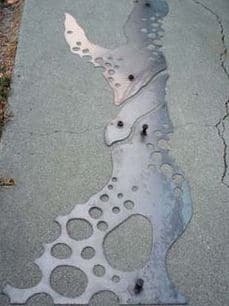
    Fig. 6: Stencil for concrete sandblasting
  5. Close all the valves of sandblaster machine and fill its tank with sand or other available materials designed for sandblasting such as soda, silica or silicon dioxide, steel grit, glass bead, and bristle blasting.
    Sandblasting material; Silica sand
    Fig. 7: Sandblasting material; Silica sand
  6. Turn on the compressor and set low pressure at the beginning; possibly a range of 275 MPa to 0.689 MPa.
  7. Direct the nozzle at the concrete, but it should be keep at a distance of 20cm to 40 cm away from the body of the operator.
  8. After that, start sandblasting of concrete surface top to bottom in order to achieve even coverage. The nozzle shall be at distance of 30.5cm from the surface till the concrete is properly cleaned and required texture is achieved. An experienced operator can quickly determine the nozzle position to produce the specified surface finish.
  9. Employ short burst of sand for difficult area and sweeping motions for other parts of the concrete.
  10. Clean the surface with compressed air after finishing the job. Collect all the utilized sand in a wheelbarrow and haul it away.

Advantages of Sandblasting

Sandblasting offers many benefits which include:
  • Cost effective
  • Efficient
  • Offer better results compare with other conventional methods
  • Fast

Seismic Design of Retaining Wall


Seismic Design of Retaining Wall


Seismic design of retaining wall is considerably complicated problem in which assumptions have to be considered in order to make indeterminable issue solvable employing theory of statics and differential calculus.
The computation of each static and dynamic pressure acting on retaining wall need more research and site selection is becoming codified. Site reports provide location peak ground acceleration only and utilization of this information is left for the designer.
Seismic Design of Retaining Wall

When seismic design of retaining wall is required?

The code or standard that followed by designer play an important role in deciding whether the seismic design of retaining wall is required or not. The earthquake design necessity is argued by some.
This is because, apart from waterfront wall where liquefaction is a possibility and walls which designed unsatisfactorily for static loads, evidence of retaining wall damage or deterioration approximately absent if the wall is designed perfectly.
Furthermore, because retaining walls are not occupied consequently does not risk life safety except retaining walls that support buildings.
However, International Building Code 2009 at section 1613 stated that every structure, and portion thereof, including nonstructural components that are permanently attached to structures and their supports and attachments, shall be designed and constructed to resist the effects of earthquake motions in accordance with ASCE 7. This obviously necessitate the design all structures for earthquake loads.
Finally, it is advised that the designer check applicable Codes of the state in which specific seismic requirements are provided.

Mononobe-Okabe Analysis of Earth Pressure

Mononobe-Okabe equation is the modification of coulomb equation and it considers seismic forces. The latter formula used to compute lateral earth pressure acts on retaining walls but it cannot be employed to calculate internal force which backfill soil impacts on the retaining walls during earthquake.
The Mononobe-Okabe formula solve coulomb equation problem by taking both horizontal and vertical ground accelerations into consideration and provide seismic coefficients for passive (KPE) and active (KAE) pressure.
Coefficient for Seismic Design of Retaining Wall
And horizontal component is Horizontal Component of Seismic Coefficient
Where:
KAE: Active earth pressure coefficient, static +seismic
Slope of Retaining Wall with Horizontal: Slope of retaining wall to horizontal (90oused for vertical face)
Slope of Backfill: slope of backfill soil
Angle of Wall Friction: Angle of wall friction
Angle of internal friction of soil:Angle of internal friction of soil
An Angle Theta: An angle whose tangent is the ground acceleration and computed by the following equation:
angle-theta-calculation
Where:
Kh: Horizontal ground acceleration
When the face of the wall is vertical and Angle of Wall Friction is considered to be theta-by-2 , equation-1 becomes:
Coefficient for Seismic Design of Retaining Wall
Total force (active and earthquake) can be calculated by the following equation:
Formula for Total Forces Acting on Retaining Wall
Where:
Density of SoilSoil density
HHeight of retaining wall
Furthermore, in case ground acceleration is equal to zero, KAE becomes the well-known coulomb KA equation.
The passive earth pressure coefficient KPE is expressed as:
Passive Earth Pressure Coefficient
It worth mentioning that passive pressure coefficient declines under seismic conditions.
KAE Consist of two components includes static and seismic. The seismic (KAE – KA) part is assumed to be an inverted triangular or trapezoidal diagram pressure with resultant force acting at 0.6H. moreover, (KA) is well known triangular distribution acting at (H/3).
Furthermore, the location of combined resultant force is could be achieved employing the following equation:
Location of Resultant Forces on Retaining Wall
It is suggested that the direction of force application per coulomb equation is tilt by an angle that is equal to the friction angle at the back face of the wall (Angle of Wall Friction) which is considered to be theta-by-2 , that is why the horizontal component is suggested to be:
Horizontal Components of Forces Acting on Retaining Wall
Safety factor for sliding and overturning when earthquake is present is 1.1.

Determining Lateral Seismic Earth Pressure (Kh)

Lateral seismic earth pressure which act against retaining wall is computed by equation Mononobe- Kobe formula using horizontal ground acceleration (Kh).
This value is designed acceleration and is less severe compare with those accelerations that could occur at site. One third to one half of peak ground acceleration is employed if an arbitrary declined value of (Kh) is not utilized.
The starting point is the determination of peak ground acceleration from Code such as International Building Code (IBC) 2009 andAmerican Standard Society of Civil Engineer (ASCE) 7-10 both have similar charts.
  • For 0.2 second select Maximum Considered Earthquake (MCE) ground motion from contours, spectral acceleration at 5 percent of critical damping, with 2 percent probability of exceedance in fifty years, note that the retaining walls are (short period) therefore 0.2 second selection.

Loads and Forces Acting on Retaining Wall and Their Calculations


Loads and Forces Acting on Retaining Wall and Their Calculations


Various types of loads and forces acts on a retaining wall and their calculation is important for its design. These forces on retaining wall depends on various factors which are discussed.

Loads and Forces Acting on Retaining Wall

There are various types of loads and forces acting on retaining wall, which are:
  1. Lateral earth pressure
  2. Surcharge loads
  3. Axial loads
  4. Wind on projecting stem
  5. Impact forces
  6. Seismic earth pressure
  7. Seismic wall self-weight forces
Retaining wall design could include any or all of loads and forces which are explained in the following sections:

1. Lateral Earth Pressure Acting on Retaining Wall

The main purpose of retaining wall construction is to retain soil that is why soil lateral earth pressure is major concern in the design. Sliding soil wedge theory is the basis for most of theories by which lateral earth pressure is computed.
The wedge theory suggests that a triangular wedge of soil would slide down if retaining wall was removed suddenly and the wall has to sustain this wedge soil. Figure 1 shows free body lateral forces acting on retaining walls.
Free body of lateral forces acting on retaining wall
Figure-1: Free body of lateral forces acting on retaining wall
Coulomb and Rankine equations are two major formulas which are used to compute lateral earth pressure:

The Coulomb method of Lateral Earth Pressure Calculation

This equation takes backfill slope, friction angle at wall face, rupture plan angle, and internal friction angle into consideration:
Coulomb method of Lateral Earth Pressure Calculation
Where:
KaCoefficient of active pressure
Angle of internal friction: Angle of internal friction
Angle of backfill slope: Angle of backfill slope
Angle of friction between soil and wall: Angle of friction between soil and wall (2?3Angle of internal frictionto 1?2Angle of internal friction is assumed)
Slope angle of the wall which is measured from horizontal : Slope angle of the wall which is measured from horizontal (equal to 90 degree for vertical wall)
Furthermore, in the case of flat level backfill soil, considering zero friction at soil-wall interface, and soil-sidewall is vertical, the coulomb equation is reduced to the following:
Coulomb Lateral Earth Pressure Coefficient

The Rankine method of Lateral Earth Pressure Calculation

This equation, which derived by William Rankine, is the development of coulomb formula. The Rankine method does not take the friction between wall and soil into account.
This makes it a conservative way for designing retaining walls. The Rankine lateral earth pressure equation is the same for both zero-wall friction and level backfill soil:
Rankine method of Lateral Earth Pressure Calculation
Where:
Backfill slope angle: Backfill slope angle
Soil internal friction angle: Internal friction angle of soil
Rankine equation is rearranged when backfill is level as:
Rankine Lateral Earth Pressure Coefficient

2. Surcharge loads Acting on Retaining Wall

Surcharge loads acting on retaining wall are additional vertical loads that used to the backfill soil above the top of the wall. It can be either dead loads for example sloping backfill above the wall height or live load which could result from highway or parking lot, paving or adjacent footing.
Live load surcharge is considered when vehicular actions act on the surface of backfill soil at a distance which equal or less than the wall height from the wall back face. Active pressure from uniform surcharge is explained in the Figure 2.
Active Forces Acting on Retaining Wall
Figure-2: Active pressure from a uniform surcharge against the retaining wall
Where:
density of soil: is the density of soil
W: is the uniform surcharge load
H: is the height of the wall
P1=Ka WH  –> Equation 7
P2=0.5KaH2   –>Equation 8

There are various types of surcharge loads such as:

  • Highway surcharges
  • Backfill compaction surcharge
  • Adjacent footing surcharge

3. Axial Forces Acting on Retaining Wall

Overturning resistance on retaining wall is provided by axial loads. There are different types of axial load that will be discussed in the following sections:

a) Vertical loads on the stem

These loads might be resulted from beam reactions, bridge, or lodger and applied to the stem directly.
For most critical conditions, it is not necessary to consider live load from dead load separately because axial live load on the stem increases resisting moments and soil bearing pressure.
Point vertical loads on walls are considered to be spread downward in a slope of two vertical to one horizontal. Consequently, there will be rather low compressive stresses at the base of the wall, girder reactions on walls is an example of vertical point load.
Moreover, bearing stresses that directly under girder or beams reactions must be checked in addition to take eccentricity into account with respect to the stem centerline since it influences stability and design of the stem.
Finally, it is worth mentioning that, un-conservative results might be produced by acting live loads at negative eccentricity toward backfill.

b) Soil weight

It is the weight of the soil above toe and heel of the retaining wall.

c) Structural weight

It includes weight of the footing and stem which added to the bearing pressure of the soil and help stability against sliding and overturning.

d) Vertical component of active pressure

It is another vertical load, resultant earth pressure action line is at an angle from horizontal provided that backfill soil is sloped.
The angle is equal to the backfill slope angle according to Rankine formula and is the same as soil-stem friction angle according to coulomb formula. This inclined active pressure has two components includes horizontal and vertical.
The latter is employed as added sliding resistance, decrease soil pressure, and increase withstand against overturning.

4. Wind Forces on Projecting Stem

Wind pressure generates an overturning force when retaining wall is exposed and extends above grade. Common formula used to compute wind pressure is as follow:
F=0.0026V2  –> Equation 9
Where:
F: wind pressure
V: Velocity of the wind
According to ASCE 7 design wind pressure (F) is calculated using the following simplified formula:
F=qz GGf    –> Equation 10
Where:
G: is the gust factor (0.85 can be used)
Gf: Commonly taken as 1.2
qz: is the velocity pressure at mid height and can be calculated using the following formula:
qz=0.613Kz Kzt Kd V2  –> Equation 11
Where:
Kz: wind directionality factor, can be determined in section 26.6 of ASCE 7-10
Kzt: Velocity pressure exposure coefficient, can be determined section 26.6 of ASCE 7-10
Kd: Topographic factor see section, can be determined 26.6 of ASCE 7-10
V: Basic wind speed in m/s

5. Impact loads Acting on Retaining Wall

Design retaining wall for car bumper might be necessary when the wall extends above grade and parking area is close to it. When retaining wall is designed for impact loads, the stem should be checked at equally spaced points along stem length from top to the bottom as impact load spread at the greater length of the stem. Moreover, use slope of two vertical to one horizontal for spreading impact load.