Tuesday, July 24, 2018

Methods of Excavation Used for Deep Foundation Construction


Methods of Excavation Used for Deep Foundation Construction

There are number of excavation methods which are used for deep foundation construction such as full open cut method, bracing excavation, anchored excavation, island excavation methods,zoned excavation, top down construction methods etc. These excavation techniques are discussed.
Methods of Excavation Used for Deep Foundation Construction
Fig.1: Excavation for Deep Foundations

Excavation Methods for Deep Foundation Construction

Full Open Cut Method

It divided into two major types including sloped full open cut as shown in Figure 2 and cantilever full open cut as illustrated in Figure 3. The former is assumed to be economical since the side of excavation would be sloped and does not need any support to held foundation wall. However, if the slope is considerably gentle or the excavation is largely deep, it will costly.
Full Open Cut Excavation with Side Slopes
Fig.2: Full Open Cut Excavation with Side Slopes
The latter needs retaining wall to support foundation wall soil and prevent collapse of foundation wall but it neither require backing nor slopes. Therefore, it cannot categorically be claimed that which method is more cost effect. The economical method may be distinguished based on analysis, design, and evaluation results.
Cantilevered Full Open Cut Excavation Method
Fig.3: Cantilevered Full Open Cut Excavation Method

Bracing Excavation Method

Bracing excavation as shown in Figure 4 is the placement of horizontal struts in front of retaining wall to held excavation wall material pressure. Bracing system consist of wale, strut, center posts, end braces, and corner braces.
Earth pressure transfer to horizontal struts through wale, and the purpose of corner and end braces is to reduce wale span without increasing strut number. Center posts prevent the failure of struts due to their own weight.
Bracing Excavation Method
Fig.4: Bracing Excavation Method

Anchored Excavation Methods

In this technique, anchors as shown in Figure 5 are installed to counter act against earth pressure. Configuration and components of anchored excavation technique are illustrated in Figure 6.
Bonded portion of the anchor provides anchoring force that works against earth pressure whereas unbonded part of the anchored transfer pressure to the anchor head. Anchor head transfer loads to the retaining wall.
The anchoring force is greatly based on the soil strength. The higher the soil strength the greater the anchoring forces. This technique is not suitable for clay and granular soil with high ground water table.
Lastly, it require short time to complete excavation with great efficiency and suitable for large areas and shallow depth.
Anchored Excavation Method
Fig.5: Anchored Excavation Method
Anchors and Different Parts of Excavation System
Fig.6: Configuration of Anchors and Different Parts of the System

Island Excavation Methods

In this method, the center of excavation area is dug and excavated material placed close to the retaining wall to create a slope. After that, the major part of the structure would be constructed at the center of the excavation. Then, the sloped soil will be excavated and struts will be placed between retaining wall and the main structure.
Finally, the struts will be removed and remaining parts of the structure will be constructed. Sometimes, it might be required to use anchored or braced technique to removed slopes soil material, specifically when the excavation is too deep.
Island Excavation Methods
Fig.7: Island excavation method explained, this method is suitable for sizable excavation area

Zoned Excavation Methods

Diaphragm walls are used as a retaining wall in the zoned excavation method. Deformation of the longer span wall would greater than short span wall as explained Figure 8.
Zoned Excavation Methods
Fig.8: Deformation of Longer Span Wall Compared to Shorter Span Ones
So, the deflections of longer span walls are declined by dividing excavation area into small area to decrease wall deformation and settlement as shown in Figure 9.
Zoned Excavation Methods
Fig.9: Dividing total excavation area into two smaller area
The excavation will begin in area B while area A would be left to support the wall of area B. then struts in area B would be installed and excavation starts in area A. This process will continue in stages till the whole excavation is completed.
It can be clearly observed that the load on diaphragm wall would be considerably large and hence deflection would great if the area had not been divided into smaller area.

Top Down Excavation Methods

In this method, construction begins from the top to the bottom of excavation and superstructure construction starts after the construction of the first slab is completed.
So, slabs are constructed after each stage of excavation is finished. The slabs play the same role as struts in holding earth pressure.
Construction process order include retaining wall construction, pile construction under column of superstructure, placing columns on piles, and installing formwork for the first slab at the top then other slabs of the would be constructed after each excavation.
This technique would need short construction time, but the cost is higher compare to other methods. Another advantage is that, construction area safer since slabs are stronger than struts.
Top Down Excavation Methods
Fig.10: Top Down Construction
Top down construction and bottom up construction
Fig.11: Comparison between top down construction and bottom up construction

Factors Affecting Selection of Excavation Methods

  • Allowable construction period
  • Construction budget
  • Availability of construction equipment
  • Existence of adjacent excavation
  • Condition of adjacent buildings
  • Type of foundation of neighboring structure
  • Construction site area
Monday, July 23, 2018

Back Filling in Foundation : Types and Procedure


Back Filling in Foundation : Types and Procedure

What Is Backfilling?

In construction, backfilling is the process of replacing or reusing the soil that is removed during building construction to strengthen and support a structure’s foundation or any other structural member.
Back Filling in Foundation

Factors affecting Backfilling in Foundation

  1. Choosing the right backfill material
  2. Compacting the backfill
  3. Period of backfilling

Types of Backfilling in Foundation

Based upon the type of material used for backfilling in foundation, they can be divided into,

Course Grained Soil

Coarse-grained soils include gravelly and sandy soils and range from clayey sands through the well-graded gravels of gravel-sand mixtures  with little or no fines.

Fine-Graded Soils Of Low To Medium Plasticity

In organic clays of low to medium plasticity (gravelly, sandy, or silty clays and lean clays) and inorganic silts and very fine sands of low plasticity (silty or clayey fine sands and clayey silts) are included in this category.

Commercial By-Products

The use of commercial by-products, such as furnace slag or fly ash as backfill material, may be advantageous where such products are locally available and where suitable natural materials cannot be found.
Fly ash has been used as a lightweight backfill behind a 25-foot-high wall and as an additive to highly plastic clay. The suitability of these materials will depend upon the desirable characteristics of the backfill in foundation and the engineering characteristics of the products.

CLSM (Controlled low strength material)

CLSM is a self-compacting, flowable, low-strength cementitious material used primarily as backfill, void fill and utility bedding as an alternative to compacted fill.
Conventional CLSM mixtures usually consist of water, Portland cement, fly ash or other similar products, fine or coarse aggregates or both. Fly ash obtained from thermal power plant was used.

Steps involved in backfilling in foundation

  1. Before you begin the backfill process, you have to be sure that the foundation cures for at least five to seven days. There are even instances when cracks may occur when you back fill too soon.
  2. The ground over which the filling has to be done should be cleaned off all grass, loose stones, rubbish of all kinds etc. If there is water in the area, it should be pumped or bailed out.
  3. Determine the types of material you will use for foundation back fill. A mixture of various materials such as rocks, soil and stone are commonly used. Some soil can retain too much moisture that is not good for your foundation.
  4. Try to use the refilling material from the excavated earth
  5. The approved excavated material, which has been stocked, shall be cleaned of all rubbish, large size stone, vegetation etc.
  6. Begin backfilling at the corners and be sure that the distribution of the soil is even so as to provide ample lateral support for the walls of your home.
  7. Use an excavator to fill in twelve inches of mixed materials on the sides of the area. After which, compress the soil and stone using the rolling compactor. You must repeat the same back fill procedure until the entire area is completely filled.
  8. Filling should be done in layers, each layer being of 15cm to 20cm.
  9. Each layer is watered and compacted with heavy rammers of wooden logs or steel.
  10. Under no circumstances black cotton soil shall be used for filling in plinth and footing pits.

Sunday, July 22, 2018

Types of Masonry Foundations, Their Construction and Uses


Types of Masonry Foundations, Their Construction and Uses

Masonry foundation may be constructed from concrete block or brick masonry units. The concrete block masonry foundation is commonly used as it is cost effective and its unattractive appearance would not be visible.
The masonry foundation should be able to adequately support weight of the structure and lateral loads imposed by soil adjacent to foundations. It should be sufficiently durable to withstand aggressions from soil and ground water.
Masonry foundation is either constructed from masonry units only (plain masonry foundation) or reinforced with steel bars to increase ultimate load carrying capacity. Different types of masonry foundations, their construction and uses are discussed.
Types of Masonry Foundation
Fig.1: Types of Masonry Foundation

Types of Masonry Foundations, Their Construction and Uses

Following are the different types of masonry foundations used in building construction:
  • Masonry strip foundation
  • Masonry spread (isolated) footing
  • Stepped masonry footing
  • Masonry inverted arch foundation

Masonry Strip Foundation

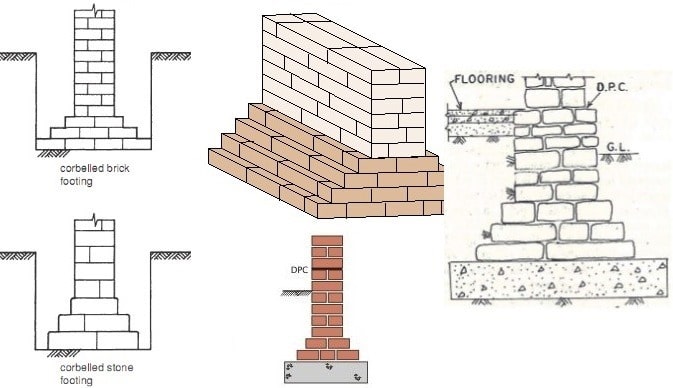
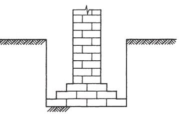
Strip masonry foundation as shown in Figure-2 and Figure-3 is constructed from brick masonry, block masonry or stone masonry directly below bearing walls. This type of masonry foundation is suitable for the location where the quality of soil material is good and acceptable.
The foundation is considerably wide at the bottom and the width would be decreased gradually up to a specific level. This will help in uniform distribution of large area and prevent cracks or damages of foundation at edge of the wall.
When the soil on which masonry strip is constructed is clay or silt, then it is required to bed the masonry units in mortar and all joints should be filled with mortar.
If mortar is not used in the construction of masonry strips placed on clay and silt, then ground water would flow through masonry joints and will soften the clay material. As a result, the masonry foundation would suffer substantial settlement.
If the bearing capacity of the soil under the foundation is poor, it is recommended to provide concrete below strip footing with preferable thickness of 100 mm to 225 mm as illustrated in Figure-4.
The dimension of strip footing is dependent on soil condition under the foundation, applied loads and construction method of the structure supported by the foundation.
Masonry Strip Foundation
Fig.2: Brick Masonry Unit Used to Construct Masonry Strip Foundation
Bricks Used for Construction of Strip Masonry Footing
Fig.3: Bricks Used for Construction of Strip Masonry Footing
Layer of Concrete Provided Beneath Strip Foundation
Fig.4: Layer of Concrete Provided Beneath Strip Foundation in Poor Bearing Capacity Soil

Masonry Spread (Isolated) Footing

Masonry spread footing is constructed from good quality bricks or stone. The bottom of isolated footing is considerably wide compared with load bearing masonry wall above.
This wider portion of spread foundation is provided to distribute applied load on a large area and hence improve stability of the structure.
Masonry spread footing is mostly used in the construction of residential building that has basements.
The design and layout of masonry isolated footing is mainly governed by the imposed loads. The foundation is considerably wide at the bottom, and the width would be decreased gradually up to a specific level.
Like masonry strip footing, a layer of concrete with thickness of 100 mm to 225 mm is recommended to be placed under isolated footing if the soil strength is not satisfactory as shown in Figure-5 and Figure-6.
Masonry Spread (Isolated) Footing
Fig.5: A Layer of Concrete Provided at the Bottom of Isolated Footing
Spread or Isolated Footing
Fig.6: Spread or Isolated Footing Constructed from Stone and an Underlying Concrete

Stepped Masonry Footing

This type of masonry foundation is the same as strip footing (special type of strip footing).
Strip foundation tends to slide down on slopped grounds due to the action or horizontal vector. Therefore, vertical steps are introduced to prevent the action of horizontal vector and subsequent sliding of foundation.
The use of vertical steps would provide horizontal bearing for the foundation and horizontal vector action would be overcome and eventually satisfactory stability would be realized.
It is considerably important to practice utmost care and attention during the construction of stepped footing to achieve excellent bond at steps especially in the cases of stone masonry. The sections of the stepped foundation need to be as long sections as possible.
Stepped Masonry Footing
Fig.7: Stepped Masonry Footing

Inverted Arch Masonry Foundation

As can be observed from Figure-8, inverted arch masonry footing consist of an inverted arch constructed from brick or stone masonry on which masonry wall or pier is placed.
This type of foundation is not common nowadays because the use of reinforced concrete has replaced this type of footing.
Inverted arch masonry footing used in the construction of multistory building, and was appropriate to be built in soft soil material.
The most outstanding challenge of considering inverted arch masonry was the construction of the inverted arch with satisfactory strength that needed substantial effort and highly skilled and experienced mason.
Inverted Arch Masonry Foundation
Fig.8: Masonry Arch Foundation

Friday, July 20, 2018

Types of Soil Excavation Tools and Machines in Construction


There are different types of soil excavation tools and machines used in construction. Excavation of soil is necessary in construction point of view and it should be done by hand tools or machineries based on the area of the land or depth of excavation.
By the process of excavation, the land is cleaned from tree roots, strums, organic impurities etc., which should harm to the foundation.

Types of Soil Excavation Tools and Machines:

Now a days, for the soil excavation there are so many equipment’s are there and these are classified into two types.
1. Hand tools
2. Machineries

Hand tools for Soil Excavation:

These are generally used for smaller depths of excavations in small areas. Man power is required to operate these tools. The tools come under this category are explained below.

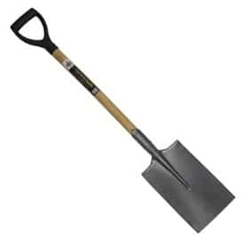
Spade

Spade is a tool which consists metal plate having sharp edges, the plate is attached to long handle which is generally made up of wood. Because of its sharp edges the soil can be dig easily. The metal plate having less curvature in the spade so, we cannot lift the soil by spade.
Types of Soil Excavation Tools - Spade

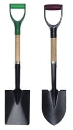
Shovel

Shovel is tool which is used for the purpose of lifting of excavated soil. It is also similar to spade the difference between spade and shovel is the difference in leading edge. The curvature of metal plate of shovel is generally higher when compared to spade so we can hold the soil easily and lifted it. Shovel can also be used for digging purpose in case of soft soils, sand etc.
Shovel

Hoe

Hoe is an excavating tool which consists a metal plate attached to a long handle with acute angle. The plate having sharp edge is used to excavate the soil. For small work of excavation it is widely preferred tool. Sometimes metal plate is replaced by fork type plate.
Hoe

Trowel

Trowel is hand sized tool which is generally used to dig the small trenches in soil or to remove the shallow roots in soil.
Trowel

Rake

Rake is a tools which is having a horizontal rod having metal teeth and is used to remove the small layers of soil.
Rake for Soil Excavation

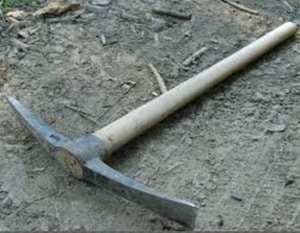
Pick axe

Pick axe consists hard spike attached perpendicular to handle. They are used for excavating small trenches in soil. Pick axe can cut the soil even if the soil is of hard type. The metal spike is pointed on one side and wide blade is provided on the other side.
Pick Axe

Mattock

This looks like pickaxe. But serious digging is not possible with mattock. Generally it is used as lifting tool because of its curve shapes metal at its bottom.
Mattock

Machinery Tools for Soil Excavation:

These are the tools which are operated by mechanical force and are used for the larger depths of excavations. There are so many types of machine tools with ease of operation are designed in this modern day period.

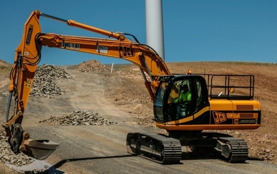
Tracked Excavator

This is also called as track hoe. It consists of cabinet and long arm. Long arm again consists of 2 parts. The first part which is closure to cabinet is called as Boom and the other part is called as Dipper-stick. Digging bucket is attached to the end of dipper. This entire system can rotate 360 degrees. In this case Vehicle is moved by traction, so we can use this equipment in mines, forestry, pipeline industries etc. the function of excavator is done by hydraulic fluid so, it is also called as hydraulic excavators.
Soil excavation machines - Tracked Excavator

Wheeled Excavator

This whole arrangement is similar to the tracked excavator except that the movement of vehicle is done by wheels. It can move quickly when compared to tracked excavator but it is not suitable for uneven grounds or hilly areas because of slippery nature. So these are generally used for road constructions etc..
Wheeled excavator

Back Hoe Excavator

In case of back hoe excavator, the hoe arrangement is on back side and loader bucket is arranged in front of the vehicle. So two operations digging and loading or lifting is done by hoe and loader. This is widely used equipment nowadays because of its small size and versatility. This is moved with the help of wheels. so, moving from one workstation to another is quickly done.
Back Hoe Excavator

Bulldozer

Bulldozer consists of hard steel plate with sharp edge at its front. This sharp edge is helps the plate to cut the soil and for excavation. The metal plate can be raised and lowered with the help of hydraulic arms. The bulldozers are available in both tracked and wheeled form. These are widely used for the works of soil excavations, weak rock strata removal, lifting of soil etc.
Bulldozer

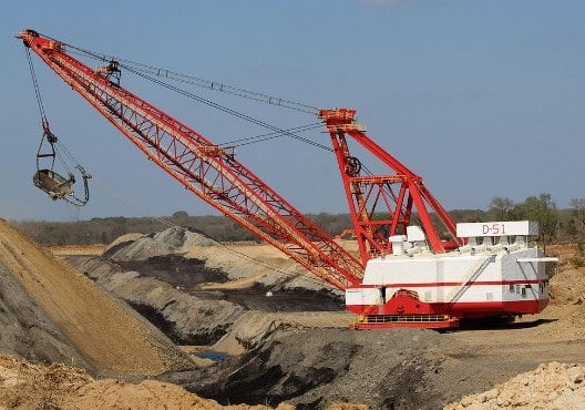
Dragline Excavators

Dragline excavators consists large length boom. A cable is hanged from the top of the boom and digging bucket is suspended to the cable. Generally dragline excavators are used for larger depth excavations like port construction, under water sediment removal etc. These are heavy equipment with greater economy.
Dragline Excavator

Trenchers

Trenchers are the equipment’s used to dig trenches in the ground. These are also available in many sizes based on our requirement. The trenches dug are generally used for drainage purpose, pipeline laying, cable laying. The trenchers are generally available in two types.
  • Chain trenchers
  • Wheeled trenchers
Chain trenchers
Chain trencher consists of a fixed arm called boom around which digging chain is arranged. The chain is very hard and consists sharp tooth. Whenever it is driven into ground the chain rotates around boom with rapid force and cuts the ground. By adjusting the angle of the boom we can manage the depth to be excavated. It cuts the soil with hard strata which cannot excavate by bucket type excavator. In case of smaller chain trenchers wheeled vehicles are available and for larger chain trenchers are available in tracked form.
Chain trenchers
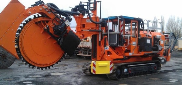
Wheeled trenchers
In case of wheeled trencher, toothed metal wheel is used as trenching tool. This equipment is available in both tracked and wheeled form of vehicles. When compared to chain trencher the wheeled trencher can cut harder soil strata. It is also used to cut pavement surface while road repair works. Economically also wheeled trencher is better than the chain trencher.
Wheeled trenchers