Friday, July 20, 2018

Types of Rebaring Equipment used for Reinforcement Works in RCC


Different types of rebaring equipment are used for cutting, bending and tying of reinforcement in reinforced concrete construction. These types of rebaring equipments are discussed in this article.
Types of Rebaring Equipment used for Reinforcement Works in RCC

Types of Rebaring Equipment used for Reinforcement Works in RCC

The below flowchart shows the process undergone in rebaring and their respective equipment available.
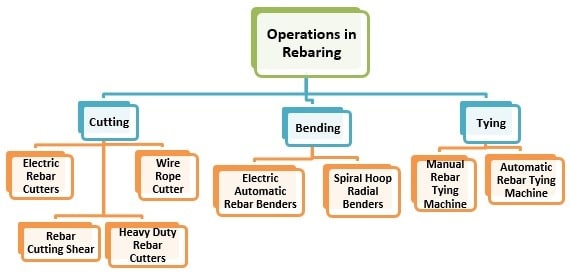
Operations in Rebaring of Reinforcement Works for RCC Construction

Reinforcement Cutting Equipments

Electric Rebar Cutters

Electric rebar cutters are bar cutting equipment that can cut bars up to 16mm diameters. They can cut bolts and high strength tensile bars. They require a charging time of 25 minutes.
When the equipment is fully charged, it can cut 75 pieces of 16mm diameter and 110 pieces of 13mm diameter bars with ease. It possess an adjustable head that can rotate in 180 degrees. The below figure shows an electric rebar cutter.
Types of Rebaring Equipment - Electric Rebar Cutter
Fig.1: Electric Rebar Cutter
Specially designed hydraulic electric motors are available which are very easy to operate. They have the advantage of no sparks or flames. They also have no large abrasive blades that make use of trailing hoses. The system make use of hydraulic oil, tool kit and a carrying case. These are portable in nature.
These helps in cutting bars that have epoxy coating (if any) within 5 seconds. These are available in 16 to 32 mm diameter cutting capacities. Here there is a knob that is adjusted as per the size of the bar placed to cut.
Electric or Hydraulic Rebar Cutting Equipment
Fig.2: Electric or Hydraulic Rebar Cutting Equipment

Heavy Duty Rebar Cutter

Heavy duty rebar cutter as the name specifies can cut bars of large diameter, up to 42mm. The equipment is highly sophisticated and developed that, it can cut three to six pieces of the bars at a single cutting. The cutter is of general type.
To ensure protection of its internal gear and for lasting performance, it has a tightly sealed oil type. The machine gains fame in its excellent power and cutting speed. The blade is treated with heat to reduce the damage of the blade during the cutting.
Heavy Duty Rebar Cutter
Fig.3: Heavy Duty Cutting Machine Example Model- TYC -D35 with the operation of cutting three pieces of bars at a single time

Wire Rope Cutters

Wire rope cutters are equipment used to cut the wire ropes under required specification. The blade used for the wire rope cutters are made of high strength steel with a coating of titanium to ensure precision and longevity of the blade.
The cutting capacity of these cutters varies from 1.5mm to 20mm diameter wire ropes. The time taken to cut the wires are 8 seconds. This equipment too gains a rotating head, that would turn in 180 degrees. The system weighs around 6.3kg.
Heavy Duty Hydraulic Wire Rope Cutters
Fig.4: Heavy Duty Hydraulic Wire Rope Cutters

Rebar Cutting Shear

The process of cutting of large number of bars on a regular basis is carried out with the help of rebar cutting shear equipment. These are machines used by large manufacturers, who bring the bars as per the demand of the engineer and specifications. Such method will give ready to use bars on site, with no cutting at the site.
The machine possesses upper and lower jaws, that is kept in such a way to hold the rebar in position. The separation of any uncut rebars or condense cut piles are done with the help of raking tines.
Rebar Cutting Shear Equipment
Fig.5: Rebar Cutting Shear Equipment

Reinforcement Bending Equipment

Electric Automatic Rebar Benders

Electric automatic rebar benders bending equipment is ideal for contractors, manufacturers and the builders who can perform the bending of bars with ease, gaining accuracy. T
his system is used both on site and in the shop by the manufacturers. The machines run quietly and work only when the bending has to be made. This would help in avoiding unnecessary wear within the machine.
The figure below shows an electric automatic rebar bending machine. The system provides us with rollers and collars that would facilitate the use of wide range of bar diameters.
Electric Automatic Rebar Bending Machine
Fig.6: Electric Automatic Rebar Bending Machine
Compared to manual bending techniques, the fatigue and injury problems with the workers are reduced. To ensure safety, flush mounted start and stop buttons are provided.
The maximum capacity of these machines is up to 32mm. The diameter of bending and bending angle varies with a different model of the machine.

Spiral Hoop Radial Benders

Spiral Hoop Radial Benders are machines that are designed for the spiral bending of reinforcement bars that have large diameters. They have two driving rolls, of which one is adjustable to help in holding different diameter bars.
Spiral Hoop Radius Bending Machine
Fig.6: Spiral Hoop Radius Bending Machine

Reinforcement Tying Equipment

Manual Rebar Tying Machines

Here the cutting, twisting, and tying of the rebar are done in place. The method involves experienced labor with handy equipment for wire tying. This method is low cost having no sort of maintenance.
This method is employed in all weather condition. Small projects make use of such methods. The tying equipment weighs almost 0.68kgs. Any combination of bar sizes can be tied by this method.
Reinforcement Tying Equipment
Fig.7: Reinforcement Tying Equipment

Automatic Rebar Tying Equipment

These are equipment that ties bars automatically for sizes up to 32mm. They take for 1.6seconds for a single tie. They have torqued adjustments; these are adjusted to have different tying tightness.
Depending on the size of the rebar, each wire spool will tie almost 120 to 200 rebars.
Automatic Rebar Tying Equipment
Fig.8: Automatic Rebar Tying Equipment

Electric Cutting and Bending Equipment for Reinforcement Works

This equipment help in undergoing the process of cutting and bending in a combination. These machines are portable in nature. The machine has a cutting speed of 180 degree, that creates a bend within 7 seconds.
Electric Reinforcement Bar cutting and Bending Equipment
Fig.9: Electric Reinforcement Bar cutting and Bending Equipment
These equipments can be used for cutting and bending of bars up to 16mm diameter range. No requirement for changing the attachments are carried out, that makes the equipment faster and easy to use.

Thursday, July 19, 2018

Stability of Slopes for Excavations in Different Soil Types


Stability of slopes in open excavation in different soil condition along with the factors that control slope stability in open excavation are discussed.
Stability of Slopes for Excavations
Fig.1: Various Excavation Condition

Factors Affecting Slope Stability in Open Excavation

  • Types of soil
  • Time during which the excavation is required to be open
  • Allowable degree of risk of slipping which is determined based on the existing structures and new constructed buildings around the excavation area.
If the surrounding facilities are significant, then it is mandatory to eliminate slippage danger since it could deteriorate structures close to the excavated area. However, a certain degree of slippage danger can be adopted if the surrounding structures are not important.

Excavation Slope Stability in Cohesive Soils

In this section, slope stability in open excavation in different types of cohesive soil will be discussed:

Slope Stability in Normally Consolidated Soils

It is theoretically proven that, open excavations in ordinary compacted soil with vertical wall can stand without the need for any supports provided that the excavation wall height does not surpass critical height.
In the case of exceeding the critical height, the stability of the soil would vary with time due to variations in pore water pressure behind the face of the excavation wall after release of lateral pressure.
The critical height of an open excavation is calculated by dividing four times un-drained shear strength of soil over its density.
If it is required to have stable excavation in normally consolidated soft to firm clay for considerably long time, then the safety factor is specified based on the severity of the risk that imposed by major slip.
The use of low safety factor would be adequate unless the major slip of the excavation wall leads to the loss of life and damaging properties at the vicinity of the construction site.
For deep excavations, it is specified to take the expense of removing considerable mass of slipped clay from the excavated area into consideration while the safety factor of the excavation is evaluated.
Finally, it is recommended to place the soil, which removed from excavation, away from the top of the slope since it could increase the possibility of the slippage. Therefore, this factor is also required to be considered while the safety of the excavation is analyzed.

Slope Stability in Stiff Clay

It can stand almost vertically with small soil mass fall due to erosion and frost damage from sandy lenses in the clay. However, if pocket lenses of water bearing sand and gravel are present in clay or when the excavation is dug steeply and cuts fissures in the clay, then a major risk would be highly likely and hence the excavation is massively unstable.
It is proven that, the spread of fissures in stiff clay would pose serious issues to the stability of slope in excavations. This is because the pore water pressure variations cannot be anticipated when the overburden pressure is removed.
The slope slippage in stiff fissured clay is either small falls due to crumbling or slipping along fissure plan or rotational shear slide of sizable mass of clay soil. When the slipping does not impose server risks to the surrounding structure, then it would acceptable to use a slope of 1:0.5.
This slope will not eliminate the risk of slippage completely but the fallen soil mass should be smaller and clearing operation should not be difficult. If the slipping creates serious risks to the structures close to the excavation area, then a slope of 1:2 to 1:2.5 should be adopted or the face of excavation wall should be supported using suitable techniques.
Finally, if the excavation is not open for long time, then it is advisable to use a sheet layer such as polyethylene or tarpaulin to the steeply excavated face to prevent the penetration of water into the trench wall and destabilize the excavation.

Excavation Slope stability in Cohesionless or Partially Cohesive Soil

In this section, the slope stability of excavations in various types of soil such as dry sand and gravel, dump sand, sandy gravel, water bearing sand, water bearing sandy soil, silt and silty sand, dry silt, and wet silt.

Dry sand and gravel

They are cohesion less soil that able to stand at a slope equal to their angle of repose disregard of the excavation depth.

Damp sands and sandy gravel

These are partially cohesive soil that able to stand vertically for a period of less than a month.
The slope stability in this type of soil may be kept through the use of protective layer like cement mortar to the surface.
Factors such as erosion due to surface water and wind or degradation die to construction works are the sources of instability of steep slopes in such soil.

Water bearing sand

As far as water bearing sand is concerned, open slope excavation in such soil is substantially unstable specifically steep slope in which water seeps from the excavation wall face at the toe and soil would collapse at the wall upper part till the stable angle is realized which ranges from 15-20 degree.
The stability of water bearing sand is more problematic when thin layer of silt or clay are present.
This is because clay or silt layer may bleed from the face and consequently jeopardize the stability of other strong layers.

Dry silt soil

It can stand vertically and the depth of excavation of more than 15m with slight cementing on the face can be achieved.
If such slopes are not cemented, then vibration would easily disturb their stability. Another undesired factor that lead to destabilize slopes in silt is the erosion due water.
So, stability of slopes in wet silt is considerably difficult because erosion due to water lead to the collapse of the excavation until a stable angle is reached.

Excavation Slope Stability in Rocks

The stability of vertical slopes in rocks is not free from problems since it is dependent on the angle of bedding plane and the extent of shattering of shattered or deteriorated rocks.
If the bedding plane slope is steep and toward the excavation area, then the slope would be unstable especially in the presence of ground water that lubricator rock planes and hence facilitate slipping.
However, if the slope of bedding plane is away from the excavation area or horizontal, then vertical slope of the excavation wall would be stable.
With regard to shattered rocks, it could lead to the collapse of the excavation wall. For example, of the disintegrated rock falls, then the intact rock rest on the shattered one would fall as well and eventually total collapse are likely to occur.

TYPES OF FOUNDATION FAILURE ON SOILS AND REMEDIES


Foundation failure can cause the building to collapse. Foundation is the first element of a building where the construction starts, but when it fails, it can cause many defects in the building including failure or collapse of the building. Repair of defects in foundations are most difficult and very costly, so it is most important to understand the types of foundation failure to avoid them by taking necessary steps before construction starts.

There are three main functions of a building foundation:

1. To sustain and safely transmit the loads from building / structure to the ground in such a way that it does not impair the stability or cause damage to the building or surrounding buildings.
2. The construction of foundations must safeguard the building against damage by physical forces generated in the subsoil.
3. Foundations must resist the chemical compounds present in soil to prevent corrosion to reinforcement.
The properties of soil have the major influence on the design, stability and sustainability of foundations to make it perform its functions.

Foundation failure due to Soil Movement:

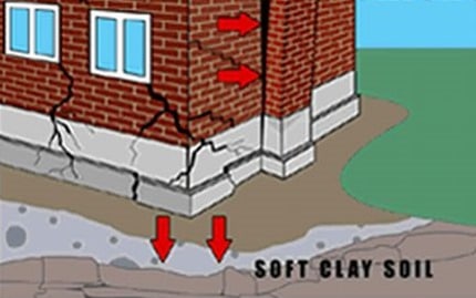
When water present between soil particles is removed, the soil tend to move closer together. When water is absorbed by soil, the soil starts to swell. This movement of soil is based on the type of soil. Large movement is seen with clayey soils than sandy soils. These kind of movement of soil due to change in water content affects the foundation settlement. Foundation tends to settle to and excessive settlement of foundation may lead to differential settlement and damage to the structure.
Soil movement can occur due to following:
1. Presence of vegetation or remains of old cut tress
2. Presence of mining areas
3. Shrinkable soils
Foundation Failure due to Settlement of Soil
Remedies for foundation failure due to soil movement:
1. Use of pile foundations where the soil is shrinkable, so that forces are transferred to the hard strata or rock.
2. Taking the foundation levels down to avoid foundation on shrinkable soils.
3. The vegetation is removed from the construction site and its roots are removed. Any cavity due to roots of vegetation shall be compacted and filled with concrete.
4. Presence of any mining areas needs to be inspected and professional help shall be taken while construction new buildings in such areas.

Foundation failure due Settlement of Soil Fill

If the building is constructed on a newly developed land by soil filling, the foundation on such soils tend to settle more with time as long time is needed for such soil to settle and become compact to resist the loads from the building foundation.
Remedies:
It shall be ensured that such soils are adequately compacted before construction begins on them. The foundation depth shall be increased to the hard strata or rock below the filled soil or pile foundations shall be used to prevent subsidence of foundation.