Friday, July 13, 2018

What is Shear Wall? – Its Types and Location in Buildings


What is a Shear Wall?

Shear wall is a structural member in a reinforced concrete framed structure to resist lateral forces such as wind forces. Shear walls are generally used in high-rise buildings subject to lateral wind and seismic forces.
In reinforced concrete framed structures the effects of wind forces increase in significance as the structure increases in height. Codes of practice impose limits on horizontal movement or sway.
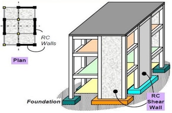
Shear Wall in a Building
Limits must be imposed on lateral deflection to prevent:
  • Limitations on the use of building,
  • Adverse effects on the behavior of non-load bearing elements,
  • Degradation in the appearance of the building,
  • Discomfort for the occupants.
Generally, the relative lateral deflection in any one storey should not exceed the storey height divided by 500.
The figure below shows the deflected profiles for a shear wall and a rigid frame.
Deflection v/s building height
One way to limit the sway of buildings and provide stability is to increase the section sizes of the members to create a rigid, moment-resisting frame.
However, this method increases storey heights, thus increasing the building cost. It is rarely used for more than 7 or 8 storeys.
Another way is to provide stiff, shear resisting walls linked to a flexible frame. These can be external walls or internal walls around lift shafts and stairwells (a core) or sometimes both are provided.
Location of Shear Wall in a Building

Structural Forms or Types of Shear Walls

Monolithic shear walls are classified as short, squat or cantilever according to their height to depth ratio.
Types of Shear Walls
Generally shear walls are either plane or flanged in section, while core walls consists of channel sections.
Structural Forms of Shear Wall
In many cases, the wall is pierced by openings. These are called coupled shear walls because they behave as individual continuous wall sections coupled by the connecting beams or slabs.
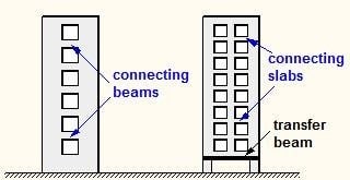
Coupled Shear Walls
Normally the walls are connected directly to the foundations. However, in a few cases where the lateral loads are relatively small and there no appreciable dynamic effects, then they can be supported on columns connected by a transfer beam to provide clear space.

Location of Shear Walls in a Building

The shape and plan position of the shear wall influences the behavior of the structure considerably. Structurally, the best position for the shear walls is in the centre of each half of the building. This is rarely practical, however, since it dictates the utilization of the space, so they are positioned at the ends.
Location of Shear Walls in a Building
positioning of shear walls inside building
This shape and position of the walls give good flexural stiffness in the short direction, but relies on the stiffness of the frame in the other direction.
This arrangement provides good flexural stiffness in both directions, but may cause problems from restraint or shrinkage. As does this arrangement with a single core, but which does not have the problem from restraint of shrinkage.
Location of Shear Wall Inside Building
However, this arrangement lacks the good torsional stiffness of the previous arrangements due to the eccentricity of the core.
If the core remains in this position then it must be designed explicitly for the torsion. It is far preferable to adopt a symmetrical arrangement to avoid this.

Diagrid Structural System – Types, Materials and Advantages


What is Diagrid Structural System?

The diagrid structural system can be defined as a diagonal members formed as a framework made by the intersection of different materials like metals, concrete or wooden beams which is used in the construction of buildings and roofs.
Diagrid structures of the steel members are efficient in providing solution both in term of strength and stiffness. But nowadays a widespread application of diagrid is used in the large span and high rise buildings, particularly when they are complex geometries and curved shapes.
Diagrid Structural System

Module Geometry of Diagrid Structural System

1. Diagrid Optimal Angle

The diagonal member of the diagrid carries both shear and moment. So the optimal angle of placing of the diagonals is dependent of building height. The optimal angle of the columns for maximum bending rigidity in the normal building is 90 degree and for the diagonals for shear rigidity is 35 degree. It is assumed that the optimal angle of the diagrid falls in between the both. Usually adopted range is 60 -70 degree. As the height of the building increases the optimal angle also increases.

2. Diagrid Module Dimensions

The module dimensions are majorly two:
  1. Height: The height of the diagrid depends on the number of floors stacked in one module of diagrid. The common number of floors stacked for module of the diagrids are 2 to 6.
  2. Base of the module: The base on which the diagrid is formed usually depends on the height and the optimal angle of the diagrid.

Diagrid Structural System Node Design

Diagrid Structural System Node Design
The nodes are the important part of the design of the diagrid system. All the diagonal sections are connected to each other by the help of nodes. These nodes are designed for two types of loads, vertical load and horizontal shear. These nodes are joined to the other sections by welding or bolting.
It is made sure that very less amount of weld is to be used in the joining. The vertical load is transferred in the form of axial loads from the diagrid members that are placed above the nodes to the gusset plate and stiffeners, then to the diagrid members below the nodes.
The horizontal shear is also in the form of axial loads in the diagrid above the nodes, but here one is in compression and another is in tension. The transfer of load is from above the node member to the gusset plate and stiffener and then from gusset plate and stiffener to the members below the node in pair of compression and tension.
Due to this load transfer path, the shear forces developed at the location of bolt connection is very high under the time of lateral loads. This may be the shear zone or weak zone of this structure during the earthquakes, the designing of the bolt connections is to be done carefully.
Diagrid Structural System Node Design

Types of Diagrid Structural System and Materials of Construction

The materials that are used in the diagrid construction are based on the following factors.
  1. Availability of material
  2. Erection time
  3. Flexibility
  4. Durability
  5. Unit weight of the material
  6. Labor cost
  7. Lead time
  8. Fire resistivity
The materials used in the construction of diagrid are

1. Steel Diagrid Structural System

The most commonly and popularly used material in the construction of diagrids is steel. The sections commonly used are rectangular HSS, rounded HSS and wide flanges. The weight and size of the sections are made so as to resist the high bending loads. They can be quickly erected and the cost of labor for the installation is low.
Steel Diagrid Structural System

2. Concrete Diagrid Structural System

The most commonly used diagrid material is concrete. The concrete diagrids are used in both type, precast and cast in-situ. As the precast concrete sections are flexible, it allows them to fit perfectly in the structure geometry. It also protects from fire damages. But the precast concrete constitutes more to the dead load of the structure.
Concrete Diagrid Structural System

3. Timber Diagrid Structural System

The least used material in the construction of diagrids is timber. This material has more disadvantages. The only advantage of this material that the section of timber are easily available in any shape and size. The installation cost is low.
The major disadvantages are that timber has lesser material strength. Durability and weathering of timber are the major issues that makes for the disadvantages of timber as a diagrid construction material.
Timber Diagrid Structural System

Advantages and Disadvantages of Diagrid Structural System

Advantages of Diagrids

The advantages of the diagrid in the construction of the structure majorly improves the aesthetic view of the building. The use of diagrid reduces the steel up to 20% compared to brace frame structure. It doesn’t need technical labor as the construction technology is simple.
The diagrid makes the maximum use if the structural material is used. When glass material is used with the diagrid, it allows generous amount of light inside the structure. These structures have majorly column free exterior and interior, free and clear, unique floor plans can be implemented.

Disadvantages of Diagrids

The major disadvantages of diagrid system are that it is still not completely explored. This construction needs a skilled labor and the present crew has no idea or the experience in installing diagrids. As the diagrid completely takes over the aesthetic appearance of the building, the design is limited only to diagrid.
The common language of floor to floor design is effected as a single diagrid stacks over 2 to 6 floors in it. Only high rise building can install diagrids. If diagrids are not properly designed or installed, it effects the economy and safety of the structure.

What is a Plinth Beam? Its purpose, Applications and Construction


Plinth beam is a reinforced concrete beam constructed between the wall and its foundation as shown in Figure-1.
Plinth Beam
Fig.1: Plinth Beam
Following topics regarding plinth beams are discussed:
  • What is the purpose of plinth beam provision?
  • Application of plinth beam
  • Concrete strength suitable for plinth beam construction
  • Dimensions of plinth beam
  • Plinth beam formwork
  • Steel bars used for plinth beam

What is the Purpose of Plinth Beam in a Building?

Plinth beam is provided to prevent the extension or propagation of cracks from the foundation into the wall above when the foundation suffers from settlement. Plinth beams distributes the load of the wall over the foundation evenly.

Applications of Plinth Beam

  • It is mandatory to provide plinth beam in areas that prone to earthquake.
  • Construction of plinth beam above the natural ground is another application of this type of beam.
Applications of Plinth Beam
Fig.2: Applications of Plinth Beam

Concrete Strength Suitable for Plinth Beam Construction

Strength of plinth beam concrete shall not be smaller than 20MPa. If concrete is mixed manually, then an extra of 20% cement need to be added to the mixture. Figure 3 show plinth beam concrete preparation placement.
Concrete for Plinth Beam
Fig.3: Concrete mix preparation and placement for plinth beam construction

Minimum Dimension of a Plinth Beam

A minimum depth of plinth beam is 20cm whereas its width should match the width of final course of the foundation.

Formwork for Plinth Beam

Formwork used for plinth beam construction should be properly installed and adequately secured prior to concrete placement as shown in Figure-4. The concrete needs to be compacted sufficiently to prevent steel bars from aggressive elements.
Formwork for Plinth Beam
Fig.4: Plinth beam shuttering is completed

Steel Bars Used for Plinth Beam

It is recommended to provide two bars with minimum diameter of 12mm at the bottom of the beam. Similarly, two bars with minimum diameter of 10mm shall be provided at the top of the plinth beam.
Reinforcement bars should be protected by 25mm concrete cover. As far as stirrups are concerned, stirrup diameter should be at least 6mm and a spacing of 15cm should be sufficient.
Steel Bars Used for Plinth Beam
Fig.5: Reinforcement installation for plinth beams are completed