There are several methods of concrete crack repair such as epoxy injection, routing and sealing, grouting, stitching, drilling and plugging, gravity filling of cracks in concrete.
Details of these methods for the selection of suitable methods for different types of crack in concrete are discussed.
How to Select Suitable Method of Concrete Crack Repair?
Suitable method for repair of cracks in concrete can be selected based on evaluation of the crack in structure for its causes. Once the cause is known and type of crack is established, then suitable method can be selected.
For example, if the cracking was primarily due to drying shrinkage, then it is likely that after a period of time the cracks will stabilize. On the other hand, if the cracks are due to a continuing foundation settlement, repair will be of no use until the settlement problem is corrected.
Methods of Concrete Crack Repair
Epoxy injection
Epoxy injection method is used for cracks as narrow as 0.002 inch (0.05 mm). The technique generally consists of establishing entry and venting ports at close intervals along the cracks, sealing the crack on exposed surfaces, and injecting the epoxy under pressure.
Epoxy injection has been successfully used in the repair of cracks in buildings, bridges, dams, and other types of concrete structures (ACI 503R). However, unless the cause of the cracking has been corrected, it will probably recur near the original crack. If the cause of the cracks cannot be removed, then two options are available.
One is to rout and seal the crack, thus treating it as a joint, or, establish a joint that will accommodate the movement and then inject the crack with epoxy or other suitable material.
With the exception of certain moisture tolerant epoxies, this technique is not applicable if the cracks are actively leaking and cannot be dried out.
Wet cracks can be injected using moisture tolerant materials, but contaminants in the cracks (including silt and water) can reduce the effectiveness of the epoxy to structurally repair the cracks.
The use of a low-modulus, flexible adhesive in a crack will not allow significant movement of the concrete structure. The effective modulus of elasticity of a flexible adhesive in a crack is substantially the same as that of a rigid adhesive because of the thin layer of material and high lateral restraint imposed by the surrounding concrete.
Epoxy injection requires a high degree of skill for satisfactory execution, and application of the technique may be limited by the ambient temperature.
Epoxy injection Procedure
Clean the cracks
The first step is to clean the cracks that have been contaminated; to the extent this is possible and practical. Contaminants such as oil, grease, dirt, or fine particles of concrete prevent epoxy penetration and bonding, and reduce the effectiveness of repairs.
Preferably, contamination should be removed by vacuuming or flushing with water or other specially effective cleaning solutions.
Seal the surfaces
Surface cracks should be sealed to keep the epoxy from leaking out before it has gelled. Where the crack face cannot be reached, but where there is backfill, or where a slab-on-grade is being repaired, the backfill material or sub base material is sometimes an adequate seal.
A surface can be sealed by applying an epoxy, polyester, or other appropriate sealing material to the surface of the crack and allowing it to harden. If a permanent glossy appearance along the crack is objectionable and if high injection pressure is not required, a strippable plastic surface sealer may be applied along the face of the crack.
When the job is completed, the surface sealer can be stripped away to expose the gloss-free surface. Cementitious seals can also be used where appearance of the completed work is important.
If extremely high injection pressures are needed, the crack can be cut out to a depth of 1/2 in. (13 mm) and width of about 3/4 in. (20 mm) in a V-shape, filled with an epoxy, and struck off flush with the surface.
Install the entry and venting ports:
Three methods are used:
- Fittings inserted into drilled holes: This method was the first to be used, and is often used in conjunction with V-grooving of the cracks. The method entails drilling a hole into the crack, approximately 3/4 in. (20 mm) in diameter and 1/2 to 1 in. (13 to 25 mm) below the apex of the V grooved section.
- Bonded flush fitting: When the cracks are not V grooved , a method frequently used to provide an entry port is to bond a fitting flush with the concrete face over the crack. The flush fitting has an opening at the top for the adhesive to enter and a flange at the bottom that is bonded to the concrete.
- Interruption in seal: Another system of providing entry is to omit the seal from a portion of the crack. This method can be used when special gasket devices are available that cover the unsealed portion of the crack and allow injection of the adhesive directly into the crack without leaking.
Mix the epoxy
This is done either by batch or continuous methods. In batch mixing, the adhesive components are premixed according to the manufacturer’s instructions, usually with the use of a mechanical stirrer, like a paint mixing paddle.
Care must be taken to mix only the amount of adhesive that can be used prior to commencement of gelling of the material.
Inject the epoxy
Hydraulic pumps, paint pressure pots, or air-actuated caulking guns may be used. The pressure used for injection must be selected carefully. Increased pressure often does little to accelerate the rate of injection.
If the crack is vertical or inclined, the injection process should begin by pumping epoxy into the entry port at the lowest elevation until the epoxy level reaches the entry port above.
For horizontal cracks, the injection should proceed from one end of the crack to the other in the same manner. The crack is full if the pressure can be maintained. If the pressure can not be maintained, the epoxy is still flowing into unfilled portions or leaking out of the crack.
Remove the surface seal
After the injected epoxy has cured, the surface seal should be removed by grinding or other means as appropriate.
Alternative procedure
For massive structures, an alternate procedure consists of drilling a series of holes [usually 7/8 to 4-in. (20 to 100-mm) diameter] that intercepts the crack at a number of locations. Typically, holes are spaced at 5-ft (1.5-m) intervals. Another method recently being used is a vacuum or vacuum assist method.
There are two techniques: one is to entirely enclose the cracked member with a bag and introduce the liquid adhesive at the bottom and to apply a vacuum at the top. The other technique is to inject the cracks from one side and pull a vacuum from the other. Typically, epoxies are used; however, acrylics and polyesters have proven successful.
Routing and Sealing of Cracks
Routing and sealing of cracks can be used in conditions requiring remedial repair and where structural repair is not necessary. This method involves enlarging the crack along its exposed face and filling and sealing it with a suitable joint sealant (Fig.1).
This is a common technique for crack treatment and is relatively simple in comparison to the procedures and the training required for epoxy injection. The procedure is most applicable to approximately flat horizontal surfaces such as floors and pavements.
However, routing and sealing can be accomplished on vertical surfaces (with a non-sag sealant) as well as on curved surfaces (pipes, piles and pole).
Routing and sealing is used to treat both fine pattern cracks and larger, isolated cracks. A common and effective use is for waterproofing by sealing cracks on the concrete surface where water stands, or where hydrostatic pressure is applied. This treatment reduces the ability of moisture to reach the reinforcing steel or pass through the concrete, causing surface stains or other problems.
The sealants may be any of several materials, including epoxies, urethanes, silicones, polysulfides, asphaltic materials, or polymer mortars. Cement grouts should be avoided due to the likelihood of cracking.
For floors, the sealant should be sufficiently rigid to support the anticipated traffic. Satisfactory sealants should be able to withstand cyclic deformations and should not be brittle.
The procedure consists of preparing a groove at the surface ranging in depth, typically, from 1/4 to 1 inch (6 to 25 mm). A concrete saw, hand tools or pneumatic tools may be used. The groove is then cleaned by air blasting, sandblasting, or waterblasting, and dried.
A sealant is placed into the dry groove and allowed to cure. A bond breaker may be provided at the bottom of the groove to allow the sealant to change shape, without a concentration of stress on the bottom (Fig.2).
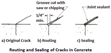
Fig.1: Routing and Sealing of Cracks in Concrete

Fig.2: Concrete Crack with Bond Breaker
The bond breaker may be a polyethylene strip or tape which will not bond to the sealant. Careful attention should be applied when detailing the joint so that its width to depth aspect ratio will accommodate anticipated movement (ACI 504R).
Concrete Crack Repair by Stitching
Stitching involves drilling holes on both sides of the crack and grouting in U-shaped metal units with short legs (staples or stitching dogs) that span the crack as shown in Fig.3. Stitching may be used when tensile strength must be reestablished across major cracks.
The stitching procedure consists of drilling holes on both sides of the crack, cleaning the holes, and anchoring the legs of the staples in the holes, with either a non shrink grout or an epoxy resin-based bonding system.

Fig.3: Concrete Crack Repair by Stitching
Additional Reinforcement for Crack Repair
Conventional reinforcement
Cracked reinforced concrete bridge girders have been successfully repaired by inserting reinforcing bars and bonding them in place with epoxy.
This technique consists of sealing the crack, drilling holes that intersect the crack plane at approximately 90 deg (Fig.4), filling the hole and crack with injected epoxy and placing a reinforcing bar into the drilled hole.
Typically, No. 4 or 5 (10 M or 15 M) bars are used, extending at least 18 in. (0.5 m) each side of the crack. The reinforcing bars can be spaced to suit the needs of the repair. They can be placed in any desired pattern, depending on the design criteria and the location of the in-place reinforcement.

Fig.4: Reinforcement bar orientation for crack repair
Prestressing steel
Post-tensioning is often the desirable solution when a major portion of a member must be strengthened or when the cracks that have formed must be closed (Fig.5).
This technique uses pre stressing strands or bars to apply a compressive force. Adequate anchorage must be provided for the prestressing steel, and care is needed so that the problem will not merely migrate to another part of the structure.

Fig.5: Prestressing Steel for Crack Repair
Drilling and Plugging Method
Drilling and plugging a crack consists of drilling down the length of the crack and grouting it to form a key (Fig.6).

Fig.6: Concrete Crack Repair by Drilling and Plugging
This technique is only applicable when cracks run in reasonable straight lines and are accessible at one end. This method is most often used to repair vertical cracks in retaining walls. A hole [typically 2 to 3 in. (50 to 75 mm) in diameter] should be drilled, centered on and following the crack.
The grout key prevents transverse movements of the sections of concrete adjacent to the crack. The key will also reduce heavy leakage through the crack and loss of soil from behind a leaking wall.
If water-tightness is essential and structural load transfer is not, the drilled hole should be filled with a resilient material of low modulus in lieu of grout. If the keying effect is essential, the resilient material can be placed in a second hole, the fiat being grouted.
Gravity Filling Method
Low viscosity monomers and resins can be used to seal cracks with surface widths of 0.001 to 0.08 in. (0.03 to 2 mm) by gravity filling. High-molecular- weight methacrylates, urethanes, and some low viscosity epoxies have been used successfully. The lower the viscosity, the finer the cracks that can be filled.
The typical procedure is to clean the surface by air blasting and/or water blasting. Wet surfaces should be permitted to dry several days to obtain the best crack filling.
Water blasting followed by a drying time may be effective in cleaning and preparing these cracks. Cores taken at cracks can be used to evaluate the effectiveness of the crack filling. The depth of penetration of the sealant can be measured.
Shear (or tension) tests can be performed with the load applied in a direction parallel to the repaired cracks (as long as reinforcing steel is not present in the core in or near the failure area). For some polymers the failure crack will occur outside the repaired crack.
Grouting Method of Crack Repair
Portland cement grouting
Wide cracks, particularly in gravity dams and thick concrete walls, may be repaired by filling with Portland cement grout. This method is effective in stopping water leaks, but it will not structurally bond cracked sections.
The procedure consists of cleaning the concrete along the crack; installing built-up seats (grout nipples) at intervals astride the crack (to provide a pressure tight connection with the injection apparatus); sealing the crack between the seats with a cement paint, sealant, or grout; flushing the crack to clean it and test the seal; and then grouting the whole area.
Grout mixtures may contain cement and water or cement plus sand and water, depending on the width of the crack.
However, the water-cement ratio should be kept as low as practical to maximize the strength and minimize shrinkage. Water reducers or other admixtures may be used to improve the properties of the grout.
For small volumes, a manual injection gun may be used; for larger volumes, a pump should be used. After the crack is filled, the pressure should be maintained for several minutes to insure good penetration.
Dry packing
Dry packing is the hand placement of a low water content mortar followed by tamping or ramming of the mortar into place, producing intimate contact between the mortar and the existing concrete.
Because of the low water-cement ratio of the material, there is little shrinkage, and the patch remains tight and can have good quality with respect to durability, strength, and water tightness.
Dry pack can be used for filling narrow slots cut for the repair of dormant cracks. The use of dry pack is not advisable for filling or repairing active cracks.
Before a crack is repaired by dry packing, the portion adjacent to the surface should be widened to a slot about 1 in. (25 mm) wide and 1 in. (25 mm) deep. The slot should be undercut so that the base width is slightly greater than the surface width.
To minimize shrinkage in place, the mortar should stand for 1/2 hour after mixing and then should be remixed prior to use. The mortar should be placed in layers about 3/8 in. (10 mm) thick.
Each layer should be thoroughly compacted over the surface using a blunt stick or hammer, and each underlying layer should be scratched to facilitate bonding with the next layer.
The repair should be cured by using either water or a curing compound. The simplest method of moist curing is to support a strip of folded wet burlap along the length of the crack.
Overlay and Surface Treatments of Cracks
Fine surface cracks in structural slabs and pavements may be repaired using either a bonded overlay or surface treatment if there will not be further significant movement across the cracks.
Unbonded overlays may be used to cover, but not necessarily repair a slab. Overlays and surface treatments can be appropriate for cracks caused by one-time occurrences and which do not completely penetrate the slab.
Surface treatments
Low solids and low-viscosity resin-based systems have been used to seal the concrete surfaces, including treatment of very fine cracks. They are most suited for surfaces not subject to significant wear.
Bridge decks and parking structure slabs, as well as other interior slabs may be coated effectively after cracks are treated by injecting with epoxy or by routing and sealing.
Materials such as urethanes, epoxies, polyesters, and acrylics have been applied in thickness of 0.04 to 2.0 in. (1 to 50 mm), depending on the material and purpose of the treatment. Skid-resistant aggregates are often mixed into the material or broadcast onto the surface to improve traction.
Overlays
Slabs containing find dormant cracks can be repaired by applying an overlay, such as polymer modified Portland cement mortar or concrete, or by silica fume concrete. Slabs with working cracks can be overlaid if joints are placed in the overlay directly over the working cracks.
In highway bridge applications, an overlay thickness as low as 1-1/4 in. (30 mm) has been used successfully. Suitable polymers include styrene butadiene or acrylic latexes. The resin solids should be at least 15 percent by weight of the Portland cement, with 20 percent usually being optimum.


