Wednesday, June 27, 2018

Types of Soil Tests for Building Construction


Types of Soil tests for building construction works depend on properties of soil. Design of foundation is based on soil test report of construction site.
Soil tests for construction of buildings or any structure is the first step in construction planning to understand the suitability of soil for proposed construction work.
Soil which is responsible for allowing the stresses coming from the structure should be well tested to give excellent performance. If soil shouldn’t tested correctly then the whole building or structure is damaged or collapsed or leaned like leaning tower of Pisa. So, soil inspection or testing is the first step to proceed any construction.
Types of Soil Tests for Building Construction

Types of Soil Tests for Building Construction

Various tests on soil are conducted to decide the quality of soil for building construction. Some tests are conducted in laboratory and some are in the field. Here we will discuss about the importance of various soil tests for building construction. The tests on soil are as follows.
  • Moisture content test
  • Atterberg limits tests
  • Specific gravity of soil
  • Dry density of soil
  • Compaction test (Proctor’s test)

Moisture Content Test on Soil

Moisture content or water content in soil is an important parameter for building construction. It is determined by several methods and they are
  • Oven drying method
  • Calcium carbide method
  • Torsion balance method
  • Pycnometer method
  • Sand bath method
  • Radiation method
  • Alcohol method
Of all the above oven drying method is most common and accurate method. In this method the soil sample is taken and weighed and put it in oven and dried at 110o 5oC. After 24 hours soil is taken out and weighed. The difference between the two weights is noted as weight of water or moisture content in the soil.
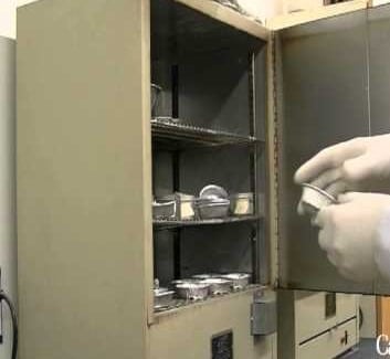
Moisture Content Test on Soil

Specific Gravity Test on Soil

Specific gravity of soil is the ratio of the unit weight of soil solids to that of the water. It is determined by many methods and they are.
  • Density bottle method
  • Pycnometer method
  • Gas jar method
  • Shrinkage limit method
  • Measuring flask method
Density bottle method and Pycnometer method are simple and common methods. In Pycnometer method, Pycnometer is weighed in 4 different cases that is empty weight (M1), empty + dry soil (M2), empty + water + dry soil (M3) and Pycnometer filled with water (M4) at room temperature. From these 4 masses specific gravity is determined by below formula.
Specific Gravity Formula for Soil

Dry Density Test on Soil

The weight of soil particles in a given volume of sample is termed as dry density of soil. Dry density of soil depends upon void ratio and specific gravity of soil. Based on values of dry density soil is classified into dense, medium dense and loose categories.
Dry density of soil is calculated by core cutter method, sand replacement method and water-displacement method.

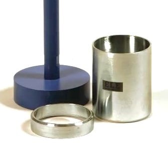
Core Cutter Method for Soil Dry Density Testing

In this methods a cylindrical core cutter of standard dimensions is used to cut the soil in the ground and lift the cutter up with soil sample. The taken out sample is weighed and noted. Finally water content for that sample is determined and dry density is calculated from the below relation.
Dry Density Calculation Formula for Soil
Dry Density Test on Soil - Core Cutter Method

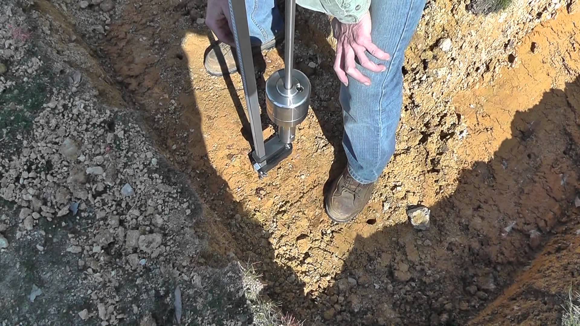
Sand Replacement Method for Soil Dry Density Testing

In this method also, a hole is created in the ground by excavating soil whose dry density is to be find. The hole is filled with uniform sand of known dry density. So by dividing the mass of sand poured into the hole with dry density of sand gives the volume of hole. So we can calculate the soil dry density from above formula.
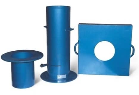
Dry Density Test on Soil - Sand Replacement Method

Atterberg Limits Test on Soil

To measure the critical water content of a fine grained soil, Atterberg provided 3 limits which exhibits the properties of fine grained soil at different conditions. The limits are liquid limit, plastic limit and shrinkage limit. These limits are calculated by individual tests as follows.

Liquid Limit Test on Soil

In this test, Casagrande’s liquid limit device is used which consist a cup with moving up and down mechanism. The cup is filled with soil sample and groove is created in the middle of cup with proper tool. When the cup is moved up and down with the help of handle the groove becomes closed at some point.
Note down the number of blows required to close the groove. After that water content of soil is determined. Repeat this procedure 3 times and draw a graph between log N and water content of soil. Water content corresponding to N=25 is the liquid limit of soil.
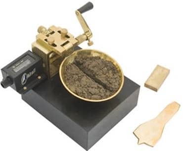
Liquid Limit Test on Soil - Casagrande's Apparatus

Plastic Limit Test on Soil

Take the soil sample and add some water to make it plastic enough to shape into small ball. Leave it for some time and after that put that ball in the glass plate and rolled it into threads of 3mm diameter.
If the threads do not break when we roll it to below 3mm diameter, then water content is more than the plastic limit. In that case reduce water content and repeat the same procedure until crumbling occurs at 3mm diameter. Finally find out the water content of resultant soil which value is nothing but plastic limit.
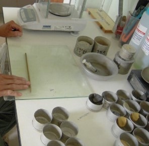
Plastic Limit Test on Soil

Shrinkage Limit Test on Soil

In case of shrinkage limit, the water content in the soil is just sufficient to fill the voids of soil. That is degree of saturation is of 100%. So, there is no change in volume of soil if we reduce the shrinkage limit. It is determined by the below formula for the given soil sample.
Shrinkage Limit Formula for Soil
Where M1 = initial mass
V1= initial volume
M2= dry mass
V2= volume after drying
Pw = density of water.

Proctor’s Compaction Test on Soil

Proctor’s test is conducted to determine compaction characteristics of soil. Compaction of soil is nothing but reducing air voids in the soil by densification. The degree of Compaction is measured in terms of dry density of soil.
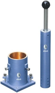
Proctor's Soil Compaction Test
In Proctor’s Compaction Test, given soil sample sieved through 20mm and 4.75 mm sieves. Percentage passing 4.75mm and percentage retained on 4.75mm are mixed with certain proportions.
Add water to it and leave it in air tight container for 20hrs. Mix the soil and divide it into 6 – 8 parts. Position the mold and pour one part of soil into the mold as 3layers with 25 blows of ramming for each layer.
Remove the base plate and Weight the soil along with mold. Remove the soil from mold and take the small portion of soil sample at different layers and conduct water content test. from the values find out the dry density of soil and water content and draw a graph between them and note down the maximum dry density and optimum water content of the compacted soil sample at highest point on the curve.
Tuesday, June 26, 2018

Methods for Repair of Small and Large Cracks in Concrete


Repair of small, medium and large cracks in concrete and repair of crushed concrete is required to enhance the strength and durability of damaged concrete members.

Repair of small and medium cracks in concrete

Small and medium cracks in reinforced concrete and masonry structures reduce their strength considerably to bear the design loads. Thus repair of such cracks is necessary to restore the designed strength of members.
The repair of small and medium cracks is done by first marking out the critical damaged zones in concrete members. Then these cracks can be repaired by injecting cement grout or chemical grouts or by providing jacketing.
The smaller cracks less than 0.75 mm width can be effectively repair by using pressure injection of epoxy.
The surface of the member near cracks is thoroughly cleaned. Loose materials are removed and plastic injection ports are placed along the length of crack at an interval equal to the thickness of the structural member. These ports are placed on both sides of the member and secured in placed with the help of epoxy seal.
When the epoxy seal has hardened, the low viscosity resin is injected into one port at a time starting from the port at lowest level and moving upwards.
The injection through port is continued till the resin flows out from the adjacent port or from the other side of the member. Then the current injection port is closed and epoxy injection is continued from the adjacent port.
Injection grouting for concrete crack repair
This process is carried out in sequence till all the ports and cracks are filled with the grout. This method can be used for all types of structural members such are beams, columns, walls and slabs.
This method can also to repair of small cracks in individual masonry blocks or for filling large continuous cracks.

Repair of Large Cracks and Crushed Concrete:

Repair of large cracks (cracks wider than 5mm) and crushed concrete and masonry structure cannot be done using pressure injection or grouting.
For repair of large cracks and crushed concrete, following procedure can be adopted:
1. The surface of cracks or crushed concrete is cleaned and all the loose materials are removed. These are then filled with quick setting cement mortar grouts.
2. If the cracks are large, then these cracks are dressed to have a V groove at both sides of the member for easy placement of grouts.
Repair of large cracks in concrete and masonry walls
Fig: Filling of cement mortar and stone chips in large cracks in masonry walls.
3. For cracks which are very large, filler materials such as stone chips can be used.
4. Additional reinforcement and shear reinforcements can be used for heavily damaged concrete members or wherever necessary based on requirements.
These additional reinforcement should be protected from corrosion by using polymer mortar or epoxy coatings.
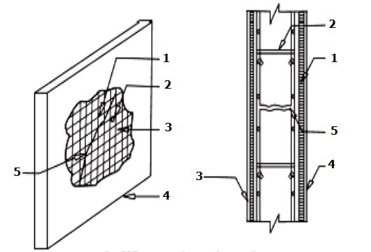
5. For damaged walls and roofs, additional reinforcement in the form of mesh is used on one side or both sides of the members. These mesh should sufficiently tied with existing members.
Reinforcement meshes in repair of roof slabs and walls
Fig: Reinforcement meshes in repair of roof slabs and walls. 1. Wire mesh on front face, 2. Clamps, 3. Wire mesh on back face, 4. Cement plaster, 5. Crack in member.
6. Stitching of cracks are done to prevent the widening of the existing cracks. In this case, holes of 6 to 10mm are drilled on both sides of the crack. Then these drilled holes are cleaned, legs of stitching dogs are anchored with short legs.
The stitching of cracks is not a method of crack repair or to gain the lost strength, this method is used to prevent the cracks from propagating and widening.

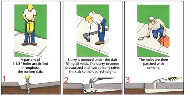
Grouting Procedure for Repair of Cracks in Concrete Structures


Grouting is a method of filling up and repair of cracks in concrete. Step by step grouting procedure needs to be followed for effective repair of concrete cracks.

Grouting Procedure for Repair of Cracks in Concrete Structures:

Procedure of grouting for repair of concrete cracks in structures are:
1. Holes  are  drilled  in  structure  along  cracks  and  in  an  around  hollow spots.
2.If  there  are  several  cracks,  holes  can  be  drilled  in  a staggered  manner  at  500  to  750mm  spacing  in  both  directions covering  adequately  the  area  proposed  to  be  grouted.  Holes spacing  can  be  altered  as  per  site  conditions.
3. G.I.  pieces  (12  to  20mm  dia  x  200mm)  with  one  end  threaded  or PVC nozzles are fixed in the holes with rich cement mortar.
4. All  the  cracks  and  annular  space  around  G.I.  pipes  are  sealed  with rich  cement  mortar.
5. All  the  cracks  are  cut  open  to  a  ‘V’  shaped groove, cleaned & sealed with rich cement mortar.
6. All  the  grout  holes  should  be  sluiced  with  water  using  the  same equipment  a  day  before  grouting  as  per  following  sequence;  so  as to saturate the masonry.
All holes are first plugged with proper wooden plugs or locked in the case  of  PVC  nozzles.  The  bottom  most  plug  and  the  two  adjacent plugs  are  removed  and  water  injected  in  the  bottom  most  hole under  pressure.
When  the  clear  water  comes  out  through  the adjacent holes the injection of water is stopped and the plugs in the bottom  most  hole  and  the  one  immediately  above  are  restored.
The  process of grouting of concrete cracks is  repeated  with  other  holes  till  all  the  holes  are covered. On  the  day  of  grouting  all  the  plugs  are  removed  to  drain out excess water and restored before commencing grouting.
The same sequence as described above is adopted for injecting the cement  grout  also.  The  grout  is  kept  fully  stirred/  agitated  under pressure  throughout  the  grouting.
The  grouting  is  carried  out  till refusal  and/  or  till  grout  starts  flowing  from  the  adjacent  hole.  A proper record of the quantity of grout injected into every hole should be maintained.
After grouting, curing should be done for14 days. Tell tales are provided for checking the effectiveness of grouting.
Only such quantities of material for preparing grout should be used, as can be used within 15 minutes of its mixing. Grouting equipment must be cleaned thoroughly after use.
Grouting Procedure for Repair of Cracks in Concrete
Fig: Grouting Procedure for Concrete Cracks Repair

Precautions during Grouting of Cracks in Concrete :

  • During  the  grouting  operation  in  track  or  close  to  it,  speed restrictions  of stop-dead  and  proceed  at  10  kmph  shall  be  imposed at the site of work and same should be continued for a period of 24 hours.
  • The restriction  may  then  be  relaxed  to  non-stop  30  kmph  to be  continued  for  a  period  of  another  2-3  days.  However,  speed restrictions indicated above are only guidelines and appropriate  speed restriction at each individual site should be considered.
  • Immediately  after  grouting  work,  all  the  grouting  equipment including  the  slurry  and  mixing  drums,  pipes,  nozzles,  etc.  should be  thoroughly  washed  so  that  set  cement  does  not  damage  the equipment.
  • After  the  work  has  been  completed,  it  should  be  inspected thoroughly  and  should  be  kept  under observation  for  a  period  of  6  months  to  12  months  for  its  behaviour after  grouting.
  • In  case  arch  masonry  of  bridges  is  grouted  to strengthen  the  structure,  some  load  tests  may  be  carried  out  in selected  cases  to  satisfy  that  grouting  has  helped  to  reduce  the deflection  of  crown  and  spread  at  the  springing  to  within permissible limits.

Repair of Dormant Cracks in Concrete


Repair of dormant cracks in concrete can be done by 4 methods such as sealing, routing and sealing, bond breaking and epoxy injection methods of crack repair.
Dormant cracks are those cracks in concrete which once occurred does not propagate or extend anymore and becomes dormant.

Repair of Dormant Cracks in Concrete

Following are the Methods of Repair for Dormant Cracks in Concrete:

Sealing of Cracks

Sealing of cracks as standalone repair should be used in conditions where structural repair is not necessary. Isolated cracks whether extending through the concrete section or partially into it, should be sealed at the concrete surfaces.
For this a slot of approx. 25mm wide should be saw cut upto 10mm deep along the crack keeping crack at the center of the slot.
The concrete should be chiseled out from between the two saw cut edges and concrete should be further undercut beyond the 10mm depth up to say 20mm depth so that the base width is slightly greater than the surface width.
After the slot is thoroughly cleaned, soaked with water for 10 hrs. and surface dried, a bond coat/ primer coat, of an approximate latex bonding compound should be applied.
Once the primer becomes tacky, high strength polymer modified cementitious mortar should be filled in the slot, properly tamped and surface finished.
Curing compound should be applied as soon as surface becomes touch dry. 7 days wet curing should be done by covering with wet Hessian and polythene sheet.

Routing and Sealing of Cracks

Alternatively, a V-groove should be prepared along the crack at the surface ranging in depth from 6 to 25mm and minimum opening at surface of 6mm (Fig. 1)
 Repair of crack by routing and sealing
Fig: Repair of crack by routing and sealing
A concrete saw, hand tools or pneumatic tools may be used. The groove is then cleaned by air blasting, sand blasting or water blasting and dried. A sealant is placed into the dry groove and allowed to cure.
The sealant may be any of several materials, including epoxies, urethanes, silicones, Polysulphide, asphaltic materials or polymer mortars.
A bond breaker may be provided at the bottom of the groove to allow the sealant to change shape, without a concentration of stress on the bottom. The bond breaker maybe polyethylene strip or tape which will not bond to the sealant.

Bond Breaking Method

In some cases, over bonding (strip coating) is used independently of or in conjunction with sealing. For this an area approx. 25 to 75mm on each side of the crack is sand blasted or cleaned by other means, and a coating (such as urethane) 1 to 2mm thick in a band is applied over the crack.
A bond breaker may be used over the crack or over a crack previously sealed (Fig. 2). Cracks subject to minimal movement may be over banded, but if significant movement can take place, sealing must be used in conjunction with over banding to ensure a waterproof repair.
Effect of bond breaker
Fig: Effect of bond breaker

Epoxy Injection Method

Cracks as narrow as 0.3mm can be bonded by the injection of epoxy successfully in buildings, bridges and other concrete structures. However, unless the cause of the cracking has been corrected, it will probably recur near the original crack.
If the cause of the crack cannot be removed and it is not causing reduction in strength of the structure, then either the crack could be sealed with flexible sealant thus treating it as a joint or establish a joint that will accommodate the movement and then the crack should be grouted with epoxy.
With the exception of certain moisture tolerant epoxies, this technique is not applicable if the cracks are actively leaking and cannot be dried out. Epoxy injection requires a high degree of skill for satisfactory execution, and the ambient temperature may limit application of the technique.