Thursday, June 14, 2018

Various Components of Staircase and their Details


There are various components or parts of a staircase which have their own functions. Each components of a staircase and their details is discussed in this article.

Various Components or Parts of Staircase and their Details

Following are the various components of staircase:

Step

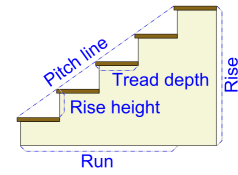
The step is composed of the tread and riser.

Tread

The part of the stairway that is stepped on. It is constructed to the same specifications (thickness) as any other flooring. The tread “depth” is measured from the outer edge of the step to the vertical “riser” between steps. The “width” is measured from one side to the other.

Riser

The vertical portion between each tread on the stair. This may be missing for an “open” stair effect.
staircase

Nosing

An edge part of the tread that protrudes over the riser beneath. If it is present, this means that, measured horizontally, the total “run” length of the stairs is not simply the sum of the tread lengths, as the treads actually overlap each other slightly.

Starting step or Bullnose

Where stairs are open on one or both sides, the first step above the lower floor may be wider than the other steps and rounded. The balusters typically form a semicircle around the circumference of the rounded portion and the handrail has a horizontal spiral called a “volute” that supports the top of the balusters.
Besides the cosmetic appeal, starting steps allow the balusters to form a wider, more stable base for the end of the handrail.
Handrails that simply end at a post at the foot of the stairs can be less sturdy, even with a thick post. A double bullnose can be used when both sides of the stairs are open.

Stringer, Stringer board or sometimes just String

The structural member that supports the treads and risers. There are typically two stringers, one on either side of the stairs; though the treads may be supported many other ways. The stringers are sometimes notched so that the risers and treads fit into them.
Stringers on open-sided stairs are often open themselves so that the treads are visible from the side. Such stringers are called “cut” stringers. Stringers on a closed side of the stairs are closed, with the support for the treads routed into the stringer.
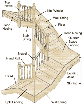
Components of Staircase
Fig: Components of Staircase

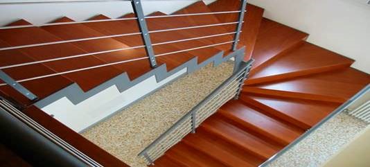
Winders

Winders are steps that are narrower on one side than the other. They are used to change the direction of the stairs without landings. A series of winders form a circular or spiral stairway. When three steps are used to turn a 90° corner, the middle step is called a kite winder as a kite-shaped quadrilateral.

Trim

Trim (e.g. quarter-round or baseboard trim) is normally applied where walls meet floors and often underneath treads to hide the reveal where the tread and riser meet. Shoe moulding may be used between where the lower floor and the first riser meet. Trimming a starting step is a special challenge as the last riser above the lower floor is rounded.
Flexible, plastic trim is available for this purpose, however wooden mouldings are still used and are either cut from a single piece of rounded wood, or bent with laminations Scotia is concave moulding that is underneath the nosing between the riser and the tread above it.

Banister, Railing or Handrail

The angled member for handholding, as distinguished from the vertical balusters which hold it up for stairs that are open on one side; there is often a railing on both sides, sometimes only on one side or not at all, on wide staircases there is sometimes also one in the middle, or even more.
The term “banister” is sometimes used to mean just the handrail, or sometimes the handrail and the balusters or sometimes just the balusters.

Volute

A handrail end element for the bullnose step that curves inward like a spiral. A volute is said to be right or left-handed depending on which side of the stairs the handrail is as one faces up the stairs.

Turnout

Instead of a complete spiral volute, a turnout is a quarter-turn rounded end to the handrail.

Gooseneck

The vertical handrail that joins a sloped handrail to a higher handrail on the balcony or landing is a gooseneck.

Rosette

Where the handrail ends in the wall and a half-newel is not used, it may be trimmed by a rosette.

Easings

Wall handrails are mounted directly onto the wall with wall brackets. At the bottom of the stairs such railings flare to a horizontal railing and this horizontal portion is called a “starting easing”. At the top of the stairs, the horizontal portion of the railing is called a “over easing”.

Core rail

Wood handrails often have a metal core to provide extra strength and stiffness, especially when the rail has to curve against the grain of the wood. The archaic term for the metal core is “core rail”.

Baluster

A term for the vertical posts that hold up the handrail. Sometimes simply called guards or spindles. Treads often require two balusters. The second baluster is closer to the riser and is taller than the first.
The extra height in the second baluster is typically in the middle between decorative elements on the baluster. That way the bottom decorative elements are aligned with the tread and the top elements are aligned with the railing angle.

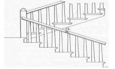
Newel

A large baluster or post used to anchor the handrail. Since it is a structural element, it extends below the floor and subfloor to the bottom of the floor joists and is bolted right to the floor joist. A half-newel may be used where a railing ends in the wall.
Visually, it looks like half the newel is embedded in the wall. For open landings, a newel may extend below the landing for a decorative newel drop.

Finial

A decorative cap to the top of a newel post, particularly at the end of the balustrade.

Base Rail or Shoe Rail

For systems where the baluster does not start at the treads, they go to a base rail. This allows for identical balusters, avoiding the second baluster problem.

Fillet

A decorative filler piece on the floor between balusters on a balcony railing.

Types of Stairs Used in Building Construction


Types of stairs used in building construction is broadly based on the shape of the stairs. Straight stairs, Turning stairs and Continuous stairs are broad types of stairs.
A stair is a set of steps leading from one floor of a building to another, typically inside the building. The room or enclosure of the building, in which the stair is located is known as staircase. The opening or space occupied by the stair is known as a stairway.

Types of Stairs – Classification of stairs:

Stairs can be broadly classified into three types:
  1. Straight stairs
  2. Turning stairs
  3. Continuous stairs

1. Straight stairs

Generally for small houses, available width is very retractable. So, this type of straight stairs are used in such conditions which runs straight between two floors. This stair may consists of either one single flight or more than one flight with a landing.
Straight stairs

2. Turning stairs

Turning stairs are sub classified as:
  1. Quarter turn stairs
  2. Half turn stairs ( dog legged stairs)
  3. Three – quarter turn stairs
  4. Bifurcated stairs

3. Quarter turn stairs

A quarter turn stair is the one which changes its direction either to the right or to the left but where the turn being affected either by introducing a quarter space landing or by providing winders. In these type of stairs the flight of stair turns 90 degrees art landing as it rises to connect two different levels. So it is also called as L-stair. Again these quarter turn stairs are two types.

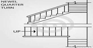
3.1. Newel quarter turn stairs

These type of stairs have clearly visible newel posts at the beginning of flight as well as at the end. At the quarter turn, there may either be quarter space landing or there may be winders.
Quarter turn stairs

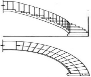
3.2. Geometrical quarter turn stairs

In geometrical stairs, the stringer as well as the handrail is continuous without any newel post at the landing area.
Quarter turn stairs

4. Half turn stairs

In case of half turn stairs its direction reversed, or changed for 180o. Such stairs are quite common. Again these are three types.

4.1. Dog-legged stairs

Because of its appearance in sectional elevation this name is given. It comes under the category of newel stairs in which newel posts are provided at the beginning and end of each flight.
Half turn stairs - Dog legged

4.2. Open newel half turn stair

In this type of open newel half turn stairs, stair has a space or well between the outer strings. This is the only aspect in which it differs from the doglegged stair.
Open newel half turn stair

4.3. Geometrical half turn stairs

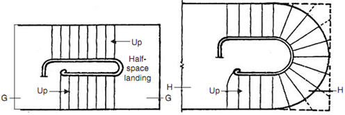
In case of geometrical half turn stairs the stringers and the hand rails are continuous, without any intervening newel post. These stairs may contains either with half space landing or without landing.
Geometrical half turn stairs

5. Three quarter turn stairs

The direction of stairs changed three times with its upper flight crossing the bottom one in the case of three quarter turn stairs. These stairs are may either be newel or open newel type. This type stairs are generally used when the vertical distance between two floors is more and as well as length of the stair room is limited.
Three quarter turn stairs

6. Bifurcated stairs

Bifurcated stairs are commonly used in public building at their entrance hall. This has a wider flight at the bottom, which bifurcates into two narrower flights, one turning to the left and other to the right, at landing.it may be either of newel type with a newel post or of geometrical type with continuous stringer and hand rails.
Bifurcated stairs

7. Continuous stairs

This type of stairs neither have any landing nor any intermediate newel post. They are geometric in shape. These are may be of following types.
  • Circular stairs
  • Spiral stairs
  • Helical stairs
Circular stairs or spiral stairs are usually made either of R.C.C or metal, and is placed at a location where there are space limitations. Sometimes these are also used as emergency stairs, and are provided at the back side of a building. These are not comfortable because of all the steps are winders and provides discomfort.
Spiral stairs
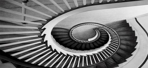
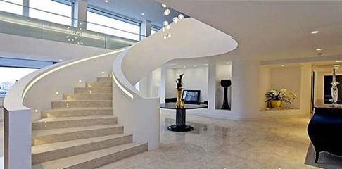
A helical stair looks very fine but its structural design and construction is very complicated. It is made of R.C.C in which a large portion of steel is required to resist bending, shear and torsion.
Helical stairs

TRANSVERSE STRENGTH TEST ON FLOORING TILES


AIM
To determine the breaking load of Terrazo flooring tiles
APPARATUS
The tile testing machine
The unit consists of an angle iron frame. A double lever system with a ratio 1:12 provided for applying the load . The lower lever is supported on ball bearing and carries a counter balanced weight and a receiving pan. The lead shots flow through a supply in to the receiving pan. The pan can be removed by just taking out a pin for transferring the lead shot to the storage pan. The storage pan is permanently fixed through the top plate.
The upper lever is connected to the lower lever by means of straps. The upper lever is held by an adjustable capstan. The adjustable loading yoke is connected to the upper lever through the vertical rods passing through the top plate. The loading yoke cross head can be locked in position after mounting the specimen.
Three 40 mm diameter rollers are provided. The self aligning bearing rollers are mounted on the metal blocks. The guide pins are fixed to the block and the corresponding holes are drilled on the top plate to adjust the centre distance of bearing rollers to 250mm and 270mm for 320mm and 345mm long tiles respectively. The third rolling roller, also of 40mm is attached to the loading yoke. The roller can be adjusted to sit centrally on the specimen while loading.
The load is applied to the specimen by allowing the lead shots to flow into the receiving pan (loading pan) through a supply pipe with valve. The orifice of the valves is adjusted to load the specimen at the rate of 45- 55 Kg /min. An L-shaped plate is attached to the lower lever, which will strike automatically on the shutter of the valve as soon as the specimen fails, there by cutting the flow of lead shots. Twelve times the weight of leadshot collected in the receiving pan gives the failure load. The counter balancing weight slides on the screw of the lower lever and can be locked in position by two nuts after balancing the lever . A stop is provided to restrict the movement of lower lever when the specimen fails.

MACHINE OPERATION
Put the counter balance weight on the screw attached to the lower lever .Adjust the loading roller along with the yoke for the specimen thickness. Adjust the counter weight so that the lower lever is in balance position.
Keeping the specimen on the loading rollers start loading the specimen by starting the flow of the lead shots. For this operate the shutter lever by pressing it down. As
soon as the specimen fails the lever strikes hard on the shutter and close the flow of leadshots.
SPECIMEN
Full size tiles – 6 No’s.
PROCEDURE
1. Dry Test for Transverse Strength
(I) Place the tile specimen (air dried) horizontally on bearers with its wearing surface uppermost and its sides parallel to the bearers.
(II) Place a plywood packing 3mm thick and 25mm wide between the tile and the bearers and also between the tile and the loading bar.
(III) Apply load to mid-span starting from zero and increase it steadily and uniformly at a rate not exceeding 200kg per metre width (measured along the bearer) per minute until the specimen fails.
(IV) Note the breaking load.
(V) Repeat the experiment on the remaining tile specimens also and take the average.
2. Wet Test for Transverse Strength.
  1. Immerse the tile specimens in water for 24 hours.
2. Take out the specimen from water and wipe to dryness.
3. Test the specimen as described in the dry test.
Note
Six tiles should be tested for dry strength and six tiles should be tested for wet strength
RESULTS
Breaking load (dry test) =
Breaking load (Wet test) =

TRANSVERSE STRENGTH TEST ON ROOFING TILES


AIM
To determine the breaking load of clay roofing tiles (Mangalore pattern)
APPARATUS
The tile testing machine
The unit consists of an angle iron frame. A double lever system with a ratio 1: 12 provided for applying the load. The lower lever is supported on ball bearing and carries a counter balanced weights and a received pan. The load shots flow through a supply pipe 950 in to the receiving pan.
The pan can be removed by just taking out a pin for transferring the load shot to the storage pan. The storage pan is permanently fixed through the top plate.
The upper lever is connected to the lower lever by means of steps. The upper lever is held by an adjustable capstan. The adjustable loading yoke is connected to the upper lever through the vertical rods passing through the top plate. The loading yoke cross head can be locked in position after mounting the specimen.
The 40mm diameter rolled are provided .The self aligning bearing rollers are mounted on the metal blocks. The guide pins are fixed to the block and the corresponding holes are drilled on the top plate to adjust the centre distance of bearing rollers to 250mm and 270 mm for 320 mm is attached to the loading yoke. The roller can be adjusted to slit centrally on the specimen while loading.
The load is applied to the specimen by allowing the load shout to flow into the receiving pan (loading pan) through a supply pipe with value. The orifice of the valves is adjusted to load the specimen at the rate of 45- 55 Kg/min. An L- shaped plate is attached to the lower lever, which will strike automatically on the shutter of the valve as soon as the specimen fails, there by cutting the flow of lead shouts. Twelve times the weight of lead shots collected in the receiving pan gives the failure load. The counter balancing weight slides on the screw of the lower and can be locked in position by two nets after balancing the lever. A stop is provided to restrict the movement of lower lever when the specimen fails.
tile testing machine
SPECIMEN
Three tiles should be used for this test from the sample selected.
PROCEDURE
(i) Put the counter balance weight on the screw attached to the lower lever.
(ii) Adjust the loading roller along with the yoke for the specimen thickness.
(iii) Adjust the counter weight so that the lower lever is in balanced position.
(iv) Keep the bearing roller at the proper centre distance according to the specimen tested.
(v) Keep the specimen on the bearing rollers.
(vi) Adjust the loading roller so that the loading roller is in contact with the specimen.
(vii) Start loading the specimen by starting the flow of lead shots. For this operate the shutter lever by pressing it down. As soon as the specimen fails the lever strikes hard on the shutter and closes the flow of lead shots.
(viii) Remove the loading pan
(ix) Weigh the lead shots collected in the pan on a balance.
(x) Multiply this weight by twelve to get the actual load at which the specimen failed.
NOTE
Keep three tiles in water at 27 ± 2°C for 24 hours. And test them in wet condition and three tiles in dry condition. Support the tiles evenly flat-wise on bearers set with a sp-an of 27 cm and resting on bottom surface. Apply load with the direction of the load perpendicular to the span at a uniform rate 25 to 55 kg/min.
RESULT
Breaking load of tile in wet condition =
Breaking load of tile in dry condition =