Monday, June 11, 2018

How to Prevent Errors During Setting Out Building Plan on Ground?


Setting out building plan on ground is one of the most significant steps in building constructions and any errors at this stage would cause considerable problems, if it is not tackled immediately.

Errors During Setting Out Building Plan on Ground

There are different types of errors that might be made when a structure is set out for example gross errors, systematic errors and random errors.
These errors should be prevented and there are some measures to tackle these issues. These measures will be discussed in the following sections.
Setting Out of Building Plan on Ground
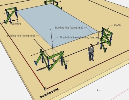
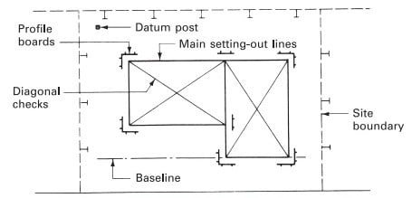
Fig.1: Setting Out of Building Plan on Ground
Errors During Setting Out Building Plan on Ground
Fig.2: Setting Out Building Plan on Ground

How to Prevent Errors During Setting Out of Building?

Following are the different types of control that should be carried out to prevent any errors during setting out building plan on ground:
  • Good practice in office
  • On site control
  • Equipment and staff
  • Checks
  • Marking the ground
  • Use of grid offset

Good Practice in Office

To successfully set out the building, it is necessary to complete office works with great accuracy. The drawing should be the latest version and if there are any changes in the drawing, it should be checked whether it influences the work in the field or not.
It is required to examine and explore the quality of information, for example, the dimensions should be checked and confirmed with structural dimensions to make sure that it is realistic.
It is recommended to conduct calculation by two independent individual since the person who check the first computation may follow procedures and does not notice errors.
If a program is used to do calculations and solving problems, the user should know the program well and have information that the software does work. The user need to understand the results adequately otherwise unacceptable errors could occur.

On site control of Setting Out Errors

It is required to check both primary baseline and bench marks to make sure that they are accurate. Approximate setting out might be used for excavation but such work with such quality cannot be accepted for concrete work which requires considerable accuracy.
It is advised to continuously check concrete benchmark station since they can be damaged by excavations.
It should be guaranteed that correct stations are used during working and this can be done by noticing and observing stations or by taking measurements to the adjacent stations.

Equipment and Staff

After accurate calculations at office are finished and good control is obtained at construction site, it is considerably crucial to use a suitable instrument and experienced staff to carry out the work and get the required accuracy.
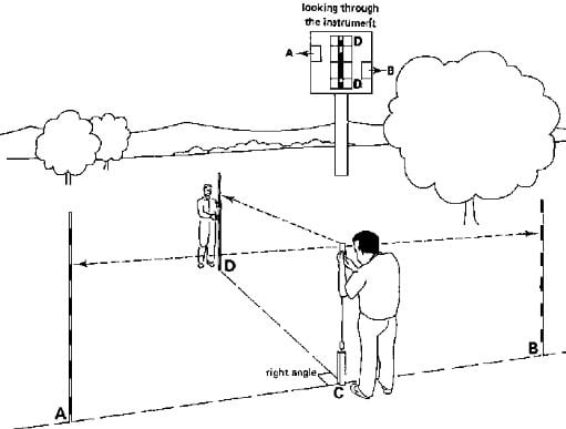
Equipment and Staff to Prevent Setting Out Errors
Fig:3: Equipment and Staff to Prevent Setting Out Errors

Checks to Prevent Setting Out Errors

It is recommended to do cross checks to specify any errors that have been made. For example, when a rectangular shape is set out, diagonals should be computed prior to the works to determine errors during the work in the field.
Cross checks need to be used for completed works to examine their accuracy and find out errors in the work if any exist.
It is advised to begin setting out from the major control lines and then proceed to other parts of the building to prevent accumulative errors.
It is recommended to establish secondary control points from the main control point instead of using other secondary control points to set a new one. This is because any error in one secondary control point would be repeated for other points and might increase.
For example, one houses is set out, it is preferable to set each house from the main control point rather than from another house since errors would cause considerable issues. In this case, there might not be enough space for the last house to be set.
Use of common sense at the end of the works is the last check that should not be avoided because great mistakes can be noticed and considerable cost could be saved.

Marking the Ground for Building Set Out

It is recommended to use mark setting out using proper means to make it easy to understand. The setting out would not serve any purpose if it cannot be understood by user.
The information provided on setting out should be adequate and the provision of too much information needs to be avoided. It is advised to ask the person that will use the setting out and find out what he wants about the work.
It is possible to use marks and expiations along the lines and on the wall unless it is a finished surface. Regarding offsets, they should be sensible and proper dimensions shall be used such as 1000mm.
It may be required to explain the setting out by the individual who carried out the work for a person who is going to use the setting out.

Use of Grid Offset

It is required to offset gridline from actual position to a new sight of line to keep the line of sight as clear as possible. This offset is recommended to be adequately large to account for size of columns and formworks.
Errors in out of square taping would be insignificant if the offset is kept small to a practical limit. In summary, no matter how offsets are established, it should not cause errors at construction site.
Regarding change in offsets, the variation should be obvious and clear such as a meter or half of a meter.
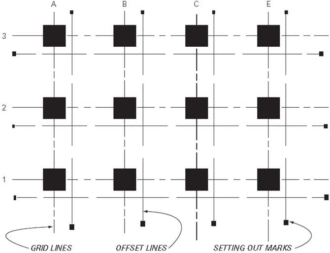
Gridline and Offset Line for Building Setting Out
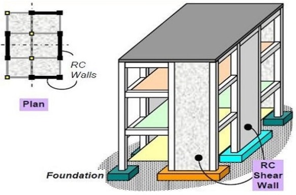
Fig.4: Gridline and Offset Line for Building Setting Out

What is Shear Wall? – Its Types and Location in Buildings


What is a Shear Wall?

Shear wall is a structural member in a reinforced concrete framed structure to resist lateral forces such as wind forces. Shear walls are generally used in high-rise buildings subject to lateral wind and seismic forces.
In reinforced concrete framed structures the effects of wind forces increase in significance as the structure increases in height. Codes of practice impose limits on horizontal movement or sway.
Shear Wall in a Building
Limits must be imposed on lateral deflection to prevent:
  • Limitations on the use of building,
  • Adverse effects on the behavior of non-load bearing elements,
  • Degradation in the appearance of the building,
  • Discomfort for the occupants.
Generally, the relative lateral deflection in any one storey should not exceed the storey height divided by 500.
The figure below shows the deflected profiles for a shear wall and a rigid frame.
Deflection v/s building height
One way to limit the sway of buildings and provide stability is to increase the section sizes of the members to create a rigid, moment-resisting frame.
However, this method increases storey heights, thus increasing the building cost. It is rarely used for more than 7 or 8 storeys.
Another way is to provide stiff, shear resisting walls linked to a flexible frame. These can be external walls or internal walls around lift shafts and stairwells (a core) or sometimes both are provided.
Location of Shear Wall in a Building

Structural Forms or Types of Shear Walls

Monolithic shear walls are classified as short, squat or cantilever according to their height to depth ratio.
Types of Shear Walls
Generally shear walls are either plane or flanged in section, while core walls consists of channel sections.
Structural Forms of Shear Wall
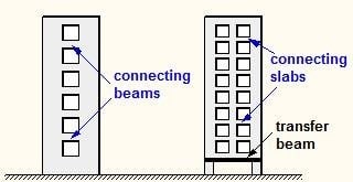
In many cases, the wall is pierced by openings. These are called coupled shear walls because they behave as individual continuous wall sections coupled by the connecting beams or slabs.
Coupled Shear Walls
Normally the walls are connected directly to the foundations. However, in a few cases where the lateral loads are relatively small and there no appreciable dynamic effects, then they can be supported on columns connected by a transfer beam to provide clear space.

Location of Shear Walls in a Building

The shape and plan position of the shear wall influences the behavior of the structure considerably. Structurally, the best position for the shear walls is in the centre of each half of the building. This is rarely practical, however, since it dictates the utilization of the space, so they are positioned at the ends.
Location of Shear Walls in a Building
positioning of shear walls inside building
This shape and position of the walls give good flexural stiffness in the short direction, but relies on the stiffness of the frame in the other direction.
This arrangement provides good flexural stiffness in both directions, but may cause problems from restraint or shrinkage. As does this arrangement with a single core, but which does not have the problem from restraint of shrinkage.
Location of Shear Wall Inside Building
However, this arrangement lacks the good torsional stiffness of the previous arrangements due to the eccentricity of the core.
If the core remains in this position then it must be designed explicitly for the torsion. It is far preferable to adopt a symmetrical arrangement to avoid this.

Methods of Measurement of Concrete Formworks for Payment Calculation


Measurements of formwork (shuttering) is required for payment to the contractor for the concrete work completed. The payment to contractor depends on whether the cost is included with the concrete construction per unit quantity or formwork is paid separately, as mentioned in the conditions of contract.
The formwork is measured in terms of area that is in contact with the concrete surface.
Measurements of formwork (shuttering)
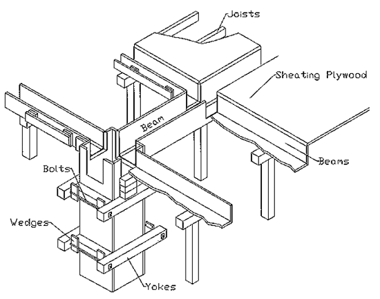
Fig: Parts of Formworks for Beams and Slabs
For example, the formwork for concrete footing will be calculated as the surface area of four sides of foundation only. Bottom of the footing is resting on earth, there is no need of any formwork and top of footing is open.
Measurements of formwork (shuttering)
Fig: Pan and Elevation of RCC Footing
From the above footing plan and elevation, it can be seen that formwork area required will be
2 x (2 + 3) x 0.6 = 6 m2
Similarly, for a reinforced concrete beam, the measurement of formwork will be taken as the combined surface area of two sides and bottom of the beam.

Issues in Formwork Measurements:

  • Normally, the forms are used more than once in concrete construction. But the payment is calculated based on the total contact area of the formwork with concrete and reuse of the forms is not taken into account. Thus, the price per unit area of formwork can be reduced for reuse of the forms. Aluminium and steel forms are reused for many number of times than wooden forms.
  • Complicated shape of concrete makes the formwork installation costlier than the simple formwork installation because of labor cost and inability to reuse these forms.
  • A construction plan is required to reuse the forms maximum number of times to make the construction cost effective.

Deduction of formwork area should not be taken for:

  • Intersection of beams
  • Intersection of beams and columns and walls
  • Any openings or cutouts in slabs

Unit of Formwork Measurement:

Formworks are measured in terms of area. So any unit such as square meter, square foot, square centimetre can be adopted. But generally, square meter and square foot of the contact area with concrete is taken as the unit of measurement. The dimensions of a formwork should be measure correct to the centimetre or inches whichever the case may be.
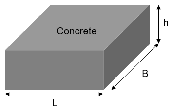
Formworks are measured as just contact area, not area of formwork, as shown below:
Measurements of formwork (shuttering)
Contact Area = 2h(L+B)

The measurements of formwork are carried out separately for each type of concrete works such as following:

a) Foundations, footings, bases of columns etc. and for mass concrete and precast shelves.
b) Walls of any thickness including attached pilasters, buttresses, plinth and string courses etc.
c) Suspended floors, roofs, landings, shelves and their supports and balconies.
d) Lintels beams, girders and cantilevers
e) Columns, pillars, posts and struts.
f) Stairs (excluding landings) except Spiral Staircase
g) Spiral staircases (including landings)
h) Arches
i) Domes, vaults, shells roofs, archribs and folded plates
j) Chimneys and shafts
k) Well steining
l) Vertical and horizontal fins individually or forming box, louvers and bands
m) Waffle or ribbed slabs
n) Edges of slabs and breaks in floors and walls
o) Cornices and mouldings