Friday, June 8, 2018

What is No-Fines Concrete? Advantages and Mix Proportion


What is No-Fines Concrete?

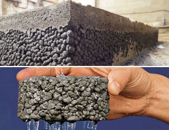
No-Fines Concrete is a lightweight concrete made up of only coarse aggregate, cement and water by omitting fines (sand or fine aggregates) from normal concrete. Advantages, limitations and mix proportions of no-fines concrete is discussed.
Very often only single sized coarse aggregate, of size passing through 20 mm retained on 10mm is used. No-fines concrete is becoming popular because of some of the advantages it possesses over the conventional concrete.
The single sized aggregates make a good no-fines concrete, which in addition to having large voids and hence light in weight, also offers architecturally attractive look.

Advantages of No-Fines Concrete

  1. No fines concrete is a lightweight concrete i.e. density is about 25 to 30% less than the normal concrete due to no fine aggregates, thus self-weight of structure is less.
  2. As it does not have sands or fine aggregates, it has less drying shrinkage compared to normal concrete
  3. It has better thermal insulating characteristic than normal concrete and thus it is useful for construction of external wall.
  4. As it has no fine aggregates, the surface area required for cement coating is reduced considerably. So, quantity of cement required gets reduced per cubic meter compared with normal concrete. So, it is economical.
  5. Lightweight concrete has no effect on quality due to segregation of coarse aggregates as it has no fine aggregates. Thus, it can be dropped from heights.
  6. No fines concrete can be compacted without the need of any types of concrete vibrators and can be easily done by tamping with rods.

Limitations of No Fines Concrete

  1. As there is no fine aggregates to fill the voids in this concrete, it has high permeability than normal concrete. Thus, it is not a good idea to construct reinforced concrete with no fines concrete, as the reinforcement can easily get corroded.
  2. To make this concrete impermeable, extra coat of masonry plaster is required, which increase the cost.
  3. No fines concrete can not be tested for workability by using tests for normal concrete such as slump or compaction factor test. Values of workability and its test methods are unknown.

Mix-proportion of No-Fines Concrete

No-fines concrete is generally made with the aggregate/cement ratio from 6 : 1 to 10 :1. Aggregates used are normally of size passing through 20 mm and retained on 10 mm.
Unlike the conventional concrete, in which strength is primarily controlled by the water/cement ratio, the strength of no-fines concrete is dependent on the water/cement ratio, aggregate cement ratio and unit weight of concrete.
The water/cement ratio for satisfactory consistency will vary between a narrow range of 0.38 and 0.52. Water/cement ratio must be chosen with care. If too low a water/cement ratio is adopted, the paste will be so dry that aggregates do not get properly smeared with paste which results in insufficient adhesion between the particles.
On the other hand, if the water/cement ratio is too high, the paste flows to the bottom of the concrete, particularly when vibrated and fills up the voids between the aggregates at the bottom and makes that portion dense. This condition also reduces the adhesion between aggregate and aggregate owing to the paste becoming very thin.
No standard method is available, like slump test or compacting factor test for measuring the consistency of no-fines concrete. Perhaps a good, experienced visual examination and trial and error method may be the best guide for deciding optimum water/cement ratio.
No-fines concrete, when conventional aggregates are used, may show a density of about 1600 to 1900 kg/m3, but when no-fines concrete is made by using lightweight aggregate, the density may come to about 360 kg/m3.
No-fines concrete does not pose any serious problem for compaction. Use of mechanical compaction or vibratory methods are not required. Simple rodding is sufficient for full compaction.
No-fines concrete does not give much side thrust to the formwork as the particles are having point to point contact and concrete does not flow. Therefore, the side of the formworks can be removed in a time interval shorter than for conventional concrete.
However, formwork may be required to be kept for a longer time, when used as a structural member, as the strength of concrete is comparatively less. The compressive strength of no-fines concrete varies between 1.4 MPa to about 14 MPa. Table 12.5 shows the compressive strength of no-fines concrete.
The bond strength of no-fines concrete is very low and, therefore, reinforcement is not used in conjunction with no-fines concrete. However, if reinforcement is required to be used in no-fines concrete, it is advisable to smear the reinforcement with cement paste to improve the bond and also to protect it from rusting.

Types of Scaffolding used in Construction


What is the scaffolding?

Scaffolding is a temporary structure to support the original structure as well as workmen used it as a platform to carry on the construction works. Types of scaffolding varies with the type of construction work. Scaffolding is made up of timber or steel. It should be stable and strong to support workmen and other construction material placed on it.

Types of Scaffolding used in Construction:

Following are types of Scaffolding in construction:
  1. Single scaffolding
  2. Double scaffolding
  3. Cantilever scaffolding
  4. Suspended scaffolding
  5. Trestle scaffolding
  6. Steel scaffolding
  7. Patented scaffolding

1. Single Scaffolding

Single scaffolding is generally used for brick masonry and is also called as brick layer’s scaffolding. Single scaffolding consists of standards, ledgers, putlogs etc., which is parallel to the wall at a distance of about 1.2 m. Distance between the standards is about 2 to 2.5 m. Ledgers connect the standards at vertical interval of 1.2 to 1.5 m. Putlogs are taken out from the hole left in the wall to one end of the ledgers. Putlogs are placed at an interval of 1.2 to 1.5 m.
Single Scaffolding in Construction

2. Double Scaffolding

Double Scaffolding is generally used for stone masonry so, it is also called as mason’s scaffolding. In stone walls, it is hard to make holes in the wall to support putlogs. So, two rows of scaffolding is constructed to make it strong. The first row is 20 – 30 cm away from the wall and the other one is 1m away from the first row. Then putlogs are placed which are supported by the both frames. To make it more strong rakers and cross braces are provided. This is also called as independent scaffolding.
Types of Scaffolding - Double Scaffolding

3. Cantilever Scaffolding

This a type of scaffolding in which the standards are supported on series of needles and these needles are taken out through holes in the wall. This is called single frame type scaffolding. In the other type needles are strutted inside the floors through the openings and this is called independent or double frame type scaffolding. Care should be taken while construction of cantilever scaffolding.
Generally cantilever scaffoldings are used under conditions such as
  • When the ground does not having the capacity to support standards,
  • When the Ground near the wall is to be free from traffic,
  • When upper part of the wall is under construction.
Types of Scaffolding - Cantilever Scaffolding

4. Suspended Scaffolding

In suspended scaffolding, the working platform is suspended from roofs with the help of wire ropes or chains etc., it can be raised or lowered to our required level. This type of scaffolding is used for repair works, pointing, paintings etc..
Suspended Scaffolding

5. Trestle Scaffolding

In Trestle scaffolding, the working platform is supported on movable tripods or ladders. This is generally used for work inside the room, such as paintings, repairs etc., up to a height of 5m.
Trestle Scaffolding

6. Steel Scaffolding

Steel scaffolding is constructed by steel tubes which are fixed together by steel couplers or fittings. It is very easy to construct or dismantle. It has greater strength, greater durability and higher fire resistance. It is not economical but will give more safety for workers. So, it is used extensively nowadays.
Steel Scaffolding

7. Patented Scaffolding

Patented scaffoldings are made up of steel but these are equipped with special couplings and frames etc., these are readymade scaffoldings which are available in the market. In this type of scaffolding working platform is arranged on brackets which can be adjustable to our required level.
Patented Scaffolding

Thursday, June 7, 2018

Common Site Problems During Masonry Construction


Masonry structure is easy to design and construct, but various site issues may occur such as incorrect mix proportions, use of unauthorized admixtures, sulphate attack, freeze and thaw cycles and aesthetic failures.

Common Site Problems During Masonry Construction

1. Incorrect Mix Proportions

Incorrect mortar mix proportions are mostly the use of less quantity of binder materials than the required amount. This problem is reported to be come up when materials are mixed at the construction site.
Commonly, applicable codes and construction documents emphasize on measuring binder material either by weight or volume, but this measure is mostly ignored when material blending is carried out on project site.
Sometimes, number of shovels is used as a measuring technique, but this practice is not accurate and lead to incorrect mix proportions. This problem cannot be tackled unless all mix constituents are accurately measure.

2. Use of Unauthorized Admixtures

This problem is the reduction of mortar quality due to the addition of air entraining admixture that take the form of domestic detergent or washing up liquids. It is likely that the strength of mortar is compromised especially in bond due to excessive air entraining.
The main motivation of adding air entrain admixture is that it improves mortar plastic properties, and mortar utilization will be substantially eased. This problem is usually encountered when materials are mixed on site.

3. Sulphate Attack

Sulphate attack occurs as result of the reaction between tricalcium present in Portland cement and soluble sulphate which may come from various sources for instance masonry units and grounds.
The reaction is expansive and the size of ettringite, which is produced because of the reaction, is greater than of the reacted materials. Consequently, spalling, degradation and finally failure could occur.
Therefore, it is necessary to take suitable measures to prevent sulphate attack. This may be achieved through preventing sulphate to reach the mortar.
It is reported that, the number of masonry units contain large amount of sulphate are reducing constantly. So, sulphates in the ground would be the major problem and the contact between ground and mortar need to be prevented. This can be achieved by practicing correct detailing of damp poof courses and related details.
Regarding exceptional situations, where sulphates occur in atmosphere and masonry units, proper measure can be considered to decrease the possibility of sulphate attack.
For example, proper designing of coping and overhangs to avoid saturations will be offer great assistance, in addition to the provision of air entraining agent.

4. Freeze and Thaw Cycles

When masonry elements saturated with water and subject to cycles of freezing and thawing, the masonry member may suffer degradation and subsequent failure.
There are certain strategies used to protect masonry members from the effect of freezing and thawing for example introduction of suitable damp proof courses and copings.
Another effective technique is to use air entraining agent in mortar which proven to be substantially advantageous. That is why most applicable codes specify the use of air entraining agent to protect masonry construction form both freezing and thawing cycles and sulfate attacks.
Effect of freezing and thawing cycles on masonry member
Fig.: Effect of freezing and thawing cycles on masonry member

5. Aesthetic Failures

Aesthetic of masonry members does not affect its load carrying capacity but it is crucial and need to be considered during design and construction.
The formation of widespread bloom or efflorescence is not acceptable by the majority of clients. Therefore, it is required to take necessary action to prevent it for example covering newly constructed masonry at the end of each day to prevent saturation, otherwise masonry member will develop disfiguring stain and hence aesthetic appearance will be compromised.
Another aesthetic problem will arise when hydrated Portland cement is not protected since it remains highly soluble and saturation will cause leaching of calcareous solution from the material.
After water evaporated from this solution, solid material will set on the surface of the unit and joints. Added to that, the leaching of calcareous solution may lead to horizontal white stain formation.

Wednesday, June 6, 2018

Various Types of Joints in Concrete Construction


Joints in concrete building construction are construction joints, expansion joints, contraction joints and isolation joints. They prevent cracking of concrete.

Types of Joints in Concrete Constructions

Types of joints in concrete constructions are:
  1. Construction Joints
  2. Expansion Joints
  3. Contraction Joints
  4. Isolation Joints

Construction Joints in Concrete

Construction joints are placed in a concrete slab to define the extent of the individual placements, generally in conformity with a predetermined joint layout.
Construction joints must be designed in order to allow displacements between both sides of the slab but, at the same time, they have to transfer flexural stresses produced in the slab by external loads.
Construction joints must allow horizontal displacement right-angled to the joint surface that is normally caused by thermal and shrinkage movement. At the same time they must not allow vertical or rotational displacements. Fig.1 summarizes which displacement must be allowed or not allowed by a construction joint.
construction-joints-in-slabs

Types of Construction Joints in Concrete Structures

Fig.2: Types of Construction Joints in Concrete Structures

Expansion joints in Concrete

The concrete is subjected to volume change due to many reasons. So we have to cater for this by way of joint to relieve the stress. Expansion is a function of length. The building longer than 45m are generally provided with one or more expansion joint. In india recommended c/c spacing is 30m. The joints are formed by providing a gap between the building parts.

Contraction Joints in Concrete

A contraction joint is a sawed, formed, or tooled groove in a concrete slab that creates a weakened vertical plane. It regulates the location of the cracking caused by dimensional changes in the slab.
Unregulated cracks can grow and result in an unacceptably rough surface as well as water infiltration into the base, subbase and subgrade, which can enable other types of pavement distress.
Contraction joints are the most common type of joint in concrete pavements, thus the generic term “joint” generally refers to a contraction joint. Contraction joints are chiefly defined by their spacing and their method of load transfer. They are generally between 1/4 – 1/3 the depth of the slab and typically spaced every 3.1 – 15 m
Contraction Joints in Concrete

Isolation Joints in Concrete

Joints that isolate the slab from a wall, column or drainpipe

Isolation joints have one very simple purpose—they completely isolate the slab from something else. That something else can be a wall or a column or a drain pipe. Here are a few things to consider with isolation joints:
Walls and columns, which are on their own footings that are deeper than the slab subgrade, are not going to move the same way a slab does as it shrinks or expands from drying or temperature changes or as the subgrade compresses a little.
Types of Joints in Concrete Construction
Even wooden columns should be isolated from the slab.
If slabs are connected to walls or columns or pipes, as they contract or settle there will be restraint, which usually cracks the slab—although it could also damage pipes (standpipes or floor drains).
Expansion joints are virtually never needed with interior slabs, because the concrete doesn’t expand that much—it never gets that hot.
Expansion joints in concrete pavement are also seldom needed, since the contraction joints open enough (from drying shrinkage) to account for temperature expansion. The exception might be where a pavement or parking lot are next to a bridge or building—then we simply use a slightly wider isolation joint (maybe ¾ inch instead of ½ inch).
Blowups, from expansion of concrete due to hot weather and sun, are more commonly caused by contraction joints that are not sealed and that then fill up with non-compressible materials (rocks, dirt). They can also be due to very long unjointed sections.
Types of Joints in Concrete Structures
Very long unjointed sections can expand enough from the hot sun to cause blowups, but this is rare.
Isolation joints are formed by placing preformed joint material next to the column or wall or standpipe prior to pouring the slab. Isolation joint material is typically asphalt-impregnated fiberboard, although plastic, cork, rubber, and neoprene are also available.
Isolation joint material should go all the way through the slab, starting at the subbase, but should not extend above the top.
For a cleaner looking isolation joint, the top part of the preformed filler can be cut off and the space filled with elastomeric sealant. Some proprietary joints come with removable caps to form this sealant reservoir.
Joint materials range from inexpensive asphalt-impregnated fiberboard to cork to closed cell neoprene. Cork can expand and contract with the joint, does not extrude, and seals out water.
Scott Whitelam with APS Cork says that the required performance is what determines the choice of joint materials. How much motion is expect, exposure to salts or chemicals, and the value of the structure would all come into play—and of course the cost.
Polyethylene foam isolation joint material comes in various colors. C2 Products
At columns, contraction joints should approach from all four directions ending at the isolation joint, which should have a circular or a diamond shaped configuration around the column. For an I-beam type steel column, a pinwheel configuration can work.
Always place the slab concrete first and do not install the isolation joint material and fill around the column until the column is carrying its full dead load.