Wednesday, June 6, 2018

Types of Sealants Used for Joints in Buildings -Properties, Uses, Working


Sealant is a material which is used to seal the joints between materials such as concrete, glass, aluminum, masonry wall etc. In general joints are provided in the structures to prevent the damage produced by stresses.
Types of Sealants Used for Joints in Buildings

Properties of Good Sealant

Different types of sealants with good properties are available. The basic properties of a good sealant should be as follows.
  • The sealant should have good bond with building materials.
  • The sealant should be soft.
  • It should be flexible.
  • It should not affected by the weather changes.
  • It should strong against stress and stress relief cycle.

Types of Sealants Used for Joints in Buildings – Properties and Uses

There are several types of sealants are:
  • Silicone based sealants
  • Urethane based sealants
  • Acrylic based sealants
  • Polysulphide based sealants
Out of the above sealants, Polysulphide sealants are more popular in construction world.

Polysulphide based Sealant

Polysulphide sealants are widely used because of good sealant properties. They are basically applied in cold conditions. Polysulphide sealants are available in two types of systems:
  • Two-part system
  • One-part system

Two-part system

This system of sealant contains two parts called base and accelerator. To prepare a sealant these both should be mixed. After mixing them both react chemically and forms thick paste. This paste should be used within 48 hours after mixing. After applying sealant it will take 8 days for full curing.
Two-part system Polysulphide sealant is available in two special forms namely, gun grade and pour grade. Gun grade is used for inclined joints, vertical joints and overhead joints while pour grade is used for horizontal joints.

One-part system

One-part system contains premixed sealant which can be directly used without any mixing. They are capable of absorbing moisture form the atmosphere and reaction occurs. In this case full curing of sealant will take 3 to 4 weeks.

Uses of Polysulphide based Sealants

Polysulphide based sealants are used in different areas of constructions as follows:
  1. Building structures joints like basements, glazing frames, ceiling joints, floors, roofs, external walls, cladding, retaining walls etc.
  2. Water retaining structures joints such as dams, reservoirs, canal linings, culverts etc.
  3. Joints in bridges, roads, aerodromes etc.
Uses of Polysulphide based Sealants

Equipment for Polysulphide based Sealants Application

Sealant should be applied with proper equipment. The equipment should be as follows:
  • Filling device
  • Gun
  • Mixer
  • Spatula
  • Backup material
  • Bond breakers
  • Masking tape

Filling Device

The mixed or prepared sealant should not be exposed to atmosphere for longer time. So, proper filling device is used and this can be attached directly to the gun for direct usage of sealant. It is well suitable for large scale works (30N or more sealant).
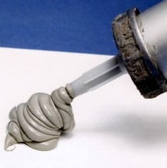
Filling Device

Gun

The gun is a device which include PVC made cartridges and nozzles to deliver the sealant. Using this gun with sealant can be easily placed in the joints in any position.
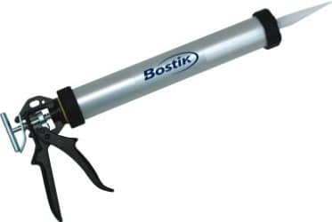
Gun

Mixer

Mixer is usually required for two-part sealant system. So, the base and accelerator should be mixed effectively.

Spatula

Spatula can be used as alternative for gun but it is suitable for small quantity works.
Along with equipment, some accessories are required for sealant which can improve its application.

Backup material

Back up material controls the depth of sealant in the joint.

Bond breakers

Bond breakers in the form a tape is made of PVC or metal or paper. Three face adhesion can be prevented by using bond breakers.

Masking tape

When the sealant is applied in the joints, the sides of joint may be damaged by spreading of sealant. To prevent this masking tape is provided on both sides of joint. Some time it may not be used if the skilled persons are working.

Working Conditions of Polysulphide based Sealants

  1. Temperature (application and service)
  2. Size of joint
  3. Storage of sealant
  4. Water resistance
  5. Chemical resistance
  6. Setting time and cure time
  7. Movement
  8. Durability

Temperature (application and service)

While applying sealant the temperature range should be 5o C to 50o C. And the sealant can work or service effectively in the temperature range of – 40o C to +80o C.

Size of joint

The width of joint should be 5 mm to 50 mm. the depth of sealant applied in the joint should be 5 mm for metal and glass structures and 10 mm for concrete and brick joints.

Storage of sealant

The mixed paste of two-part system sealant can be stored up to 12 months in dry and cool place in closed container.

Water resistance

After full curing the sealant will resist water and impermeable.

Chemical resistance

Chemical resistance of sealant is very great and they offer great resistance against oils, petrol, white spirit, fuels etc.

Setting time and curing time

The setting time and curing time will depends mainly on the temperature of that particular location. These times for different temperatures is given below.
Temperature (oC)5152535
Setting time (hours)7236188
Curing time8 weeks4 weeks2 weeks8 days

Movement

Movement of sealant after applying is 25% for butt joints and 50% lap joints.

Durability

In traffic surfaces such as roads, bridges the sealant can last up to 10 years while in other cases it can last up to 25 years.
What is Shrinkage Cracks in Concrete? -Types and Causes of Shrinkage Cracks


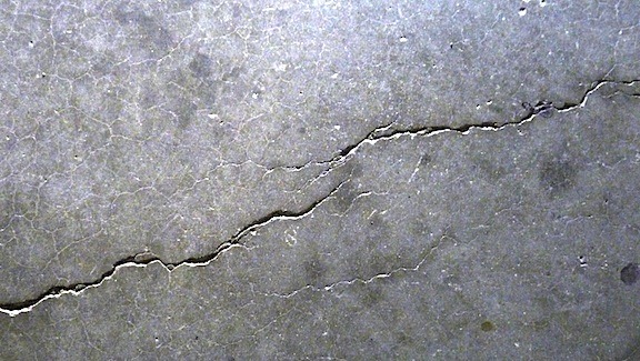
Shrinkage cracks in concrete occur due to change in moisture of concrete. Concrete and mortar are porous in their structure in the form of inter-molecular space. They expand when they absorb the moisture and shrink when they dry. This is the main cause of concrete shrinkage cracks on drying.
Shrinkage of concrete is an irreversible process.

Types of Shrinkage in Concrete

There are two types of shrinkage in concrete:
  1. Initial Shrinkage
  2. Plastic Shrinkage
Shrinkage Cracks in Concrete

Initial Shrinkage Cracks in Concrete

Initial shrinkage cracks in concrete normally occurs in all building materials or components that are cement/lime based such as concrete, mortar, masonry units, masonry and plaster etc. and is one of the main cause of cracking in structure.
Initial shrinkage in concrete and mortar occurs during construction of structural member due to drying out of moisture. The initial shrinkage of concrete is partly reversible if the moisture is maintained in concrete, but it becomes irreversible when concrete becomes dry.
During curing, due to subsequent wetting and drying this shrinkage exceeds and crack is developed in concrete.
Extent of Initial Shrinkage in Concrete
The extent of initial shrinkage in cement concrete and cement mortar depends on a number of factors namely :
a) Cement content –It increases with richness of mix.
b) Water content – Greater the water quantity used in the mix, greater is the shrinkage.
c) Maximum size, grading & quality of aggregate –With use of largest possible max. size of aggregate in concrete and with good grading, requirement of water for desired workability is reduced, with consequent less shrinkage on drying due to reduction in porosity. E.g., for the same cement aggregate ratio, shrinkage of sand mortar is 2 to 3 times that of concrete using 20 mm maximum size aggregate and 3 to 4 times that of concrete using 40 mm maximum size aggregate.
d) Curing –if the proper curing is carried out as soon as initial set has taken place and is continued for at least 7 to 10 days then the initial shrinkage is comparatively less. When the hardening of concrete takes place under moist environment there is initially some expansion which offsets a part of subsequent shrinkage.
e) Presence of excessive fines in aggregates –The presence of fines increases specific surface area of aggregate & consequently the water requirement for the desire workability, with increase in initial shrinkage.
f) Chemical composition of cement – Shrinkage is less for the cement having greater proportion of tri-calcium silicate and lower proportion of alkalis i.e. rapid hardening cement has greater shrinkage than ordinary port-land cement.
g) Temperature of fresh concrete and relative humidity of surroundings – With reduction in the surrounding temperature the requirement of water for the same slump/workability is reduced with subsequent reduction in shrinkage. Concreting done in mild winter have much less cracking tendency than the concreting done in hot summer months. In cement concrete 1/3rd of the shrinkage take place in the first 10 days, ½ within one month and remaining ½ within a year time. Therefore, shrinkage cracks in concrete continue to occur and widens up to a year period.

Plastic Shrinkage Cracks in Concrete

Plastic shrinkage in concrete occurs immediately after concrete has been placed due to settlement of large solid particles by gravity action. Due to this, water in the concrete rises to the surface. This process is also called bleeding of concrete. Bleeding in concrete continues till the layer of water on the surface of concrete has set.
As long as the rate of evaporation is lower than the rate of bleeding, there is a continuous layer of water at the surface known as “water sheen”, and shrinkage does not occur.
When the concrete surface loses water faster than the bleeding action bring it to the top, shrinkage of top layer takes place, and since the concrete in plastic state can’t resist any tension, cracks develops on the surface. These cracks are common in slabs.
The extent of plastic shrinkage depends on:
  • Temperature of concrete,
  • Exposure to the heat from sun radiation,
  • Relative humidity of ambient air and velocity of wind.

Types of Design and Detailing Errors in Construction and their Prevention


Common design and detailing errors in construction arises due to either inadequate structural design or due to lack of attention to relatively minor design details.

Types of Design and Detailing Errors in Construction and their Prevention

Types of Design and Detailing Errors in Construction and their Prevention
Following are the different design and detailing errors in construction, their symptoms and prevention methods:

(1) Inadequate structural design

Due to inadequate structural design the concrete is exposed to greater stress than it can handle or strain in concrete increases more than its strain capacity and fails.
The symptoms of such kind of failures due to inadequate structural design shows either spalling of concrete or cracking of concrete. Excessively high compressive stress due to inadequate structural design results in spalling of concrete. Also, high torsion or shear stresses results in spalling or cracking of concrete. High tensile stresses also results in cracking of concrete.
To identify the inadequate design as cause of the structural damage, the structure shall be inspected and locations of the damage should be compared to the types of stresses that should be present in the concrete. For rehabilitation projects, thorough petrographic analysis and strength testing of concrete from elements to be reused will be necessary.
Prevention: Inadequate structural design can be prevented by thorough and careful review of all design calculations. Any rehabilitation method that makes use of existing concrete structural members must be carefully reviewed.
Design and Detailing Errors in Construction

(2) Poor design details

Poor design details can cause localized concentration of high stresses in structural members even if the design is adequate to meet the requirements. These high stresses may lead to cracking of concrete that allows water or chemicals to pass through the concrete. Thus poor design detail may lead to seepage through the structural members.
Poor design detail may not lead to structural failure, but it can become the cause of deterioration of concrete. These problems can be prevented by a thorough and careful review of plans and specifications for the construction work.
Types of poor design detailing and their possible effects on structures are discussed below:

(a) Abrupt changes in section:

Abrupt changes in section may cause stress concentrations that may result in cracking. Typical examples would include the use of relatively thin sections rigidly tied into massive sections or patches and replacement concrete that are not uniform in plan dimensions.

(b) Insufficient reinforcement at corners and openings:

Corners and openings also tend to cause stress concentrations that may cause cracking. In this case, the best prevention is to provide additional reinforcement in areas where stress concentrations are expected to occur.

(c) Inadequate provision for deflection:

Deflections in excess of those anticipated may result in loading of members or sections beyond the capacities for which they were designed. Typically, these loadings will be induced in walls or partitions, resulting in cracking.

(d) Inadequate provision for drainage:

Poor attention to the details of draining a structure may result in the ponding of water. This ponding may result in leakage or saturation of concrete. Leakage may result in damage to the interior of the structure or in staining and encrustations on the structure. Saturation may result in severely damaged concrete if the structure is in an area that is subjected to freezing and thawing.

(e) Insufficient travel in expansion joints:

Inadequately designed expansion joints may result in spalling of concrete adjacent to the joints. The full range of possible temperature differentials that a concrete may be expected to experience should be taken into account in the specification for expansion joints. There is no single expansion joint that will work for all cases of temperature differential.

(f) Incompatibility of materials:

The use of materials with different properties (modulus of elasticity or coefficient of thermal expansion) adjacent to one another may result in cracking or spalling as the structure is loaded or as it is subjected to daily or annual temperature variations.

g) Neglect of creep effect:

Neglect of creep may have similar effects as described for inadequate provision for deflections. Additionally, neglect of creep in prestressed concrete members may lead to excessive prestress loss that in turn results in cracking as loads are applied.

(h) Rigid joints between precast units:

Designs utilizing precast elements must provide for movement between adjacent precast elements or between the precast elements and the supporting frame. Failure to provide for this movement can result in cracking or spalling.

(i) Unanticipated shear stresses in piers, columns, or abutments:

If, through lack of maintenance, expansion bearing assemblies are allowed to become frozen, horizontal loading may be transferred to the concrete elements supporting the bearings. The result will be cracking in the concrete, usually compounded by other problems which will be caused by the entry of water into the concrete.

(j) Inadequate joint spacing in slabs:

This is one of the most frequent causes of cracking of slabs-on-grade.

Monday, June 4, 2018

Reinforced Concrete Slab Design and Detailing Guide IS456: 2000


Reinforced concrete slab design and detailing guidelines for depth of slab, loads on slab, reinforcement guide for one-way and two-way slabs as per IS 456:2000 have been tried to present here.
Following are the RCC Slab Design and Detailing guidelines:

Reinforced Concrete Slab Design Guidelines

a) Effective span of slab:

Effective span of slab shall be lesser of the two
  1. L = clear span + d (effective depth)
  2. L = Center to center distance between the support

b) Depth of slab:

The depth of slab depends on bending moment  and deflection  criterion.  the trail depth can be obtained using:
  • Effective depth d= Span /((L/d)Basic x modification factor)
  • For obtaining modification factor, the percentage of steel for slab can be assumed from 0.2 to 0.5%.
  • The effective depth d of two way slabs can also be  assumed using cl.24.1,IS 456 provided short span is <3.5m and loading class is <3.5KN/m2
Type of supportFe-250Fe-415
Simply supportedL/35L/28
Continuous supportL/40L/32
Or, the following thumb rules can be used:
  • One way slab d=(L/22) to (L/28).
  • Two way simply supported slab d=(L/20) to (L/30)
  • Two way restrained slab d=(L/30) to (L/32)

c) Load on slab:

The load on slab comprises of Dead load, floor finish and live load. The loads are calculated per unit area (load/m2).
Dead load = D x 25 kN/m2 ( Where D is thickness of slab in m)
Floor finish (Assumed as)= 1 to 2 kN/m2
Live load (Assumed as) = 3 to 5 kN/m2(depending on the occupancy of the building)
concrete-slab

Detailing Requirements of Reinforced Concrete Slab as per IS456: 2000

a) Nominal Cover:

For Mild exposure – 20 mm
For Moderate exposure – 30 mm
However, if the diameter of bar do not exceed 12 mm, or cover may be reduced by 5 mm. Thus for main reinforcement up to 12 mm diameter bar and for mild exposure, the nominal cover is 15 mm.

b) Minimum reinforcement:

The reinforcement in either direction in slab shall not be less than
  • 0.15% of the total cross sectional area for Fe-250 steel
  • 0.12% of the total cross-sectional area for Fe-415 & Fe-500 steel.

c) Spacing of bars:

The maximum spacing of bars shall not exceed
  • Main Steel – 3d or 300 mm whichever is smaller
  • Distribution steel –5d or 450 mm whichever is smaller Where, ‘d’ is the effective depth of slab. Note: The minimum clear spacing of bars is not kept less than 75 mm (Preferably 100 mm) though code do not recommend any value.

d) Maximum diameter of bar:

The maximum diameter of bar in slab, shall not exceed D/8, where D is the total thickness of slab.