Saturday, June 2, 2018

Brick Calculator -Calculate Number of Bricks for Walls, Columns, Foundations


This brick calculator provides the calculation for number of bricks required for masonry walls, columns, foundations etc. Also, how to calculate number of bricks manually is discussed.

Standard Sizes of Bricks

Standard sizes of bricks in India are 190mm x 90mm x 90mm. and in United States is 7.5inch x 3.5 inch x 3.5 inch without mortar. In the calculator below, you can input your bricks sizes to find the number of bricks.

Number of Brick Calculator

Select Unit System*
Note: Thickness of mortar 10mm for Metric system, 1/2 inch for U.S. standard feet system is considered for dimension of bricks below.
Note: Provide Thickness of Brick Masonry without plaster thickness.

Results of Brick Calculator

Volume of Brick Masonry =
Number of Bricks Required = No’s
Volume of Mortar Required =
Note: Thickness of mortar of 10mm is considered for Metric system and 1/2 inch is considered for United States Standard Feet System.
Brick Calculator

How to Calculate Number of Bricks for Masonry Works

A brick masonry construction uses mortar as binding material for bricks. The volume of mortar used in masonry works generally ranges from 25 to 30 % of brick masonry volume.
The thickness of mortar in brickwork is generally assumed to be 10mm or ½ inch thick. With mortar thickness, the size of such a brick becomes 200 mm x 100 mm x 100 mm (8 inch x 4 inch x 4 inch) and it is known as the nominal size of the modular brick.
For calculating the number of bricks, the thickness of plaster should be deducted from the thickness of masonry construction. For example, for a brick wall of 230mm thick, the actual thickness without plaster would be 200mm, i.e. one brick thick.

Number of Bricks for Masonry Wall

In Metric System:

Consider a wall with 5m length, 4m height and 200mm thickness.
Volume of brick masonry in wall = 5 x 4 x 0.2 = 4m3
Volume of one brick with mortar = 0.2 x 0.1 x 0.1 = 0.002 m3
Number of bricks = [Volume of brick masonry / volume of one brick] = 4 / 0.002 = 2000 bricks.
Thus, number of bricks required per cubic meter = 500.

In United States Standard Feet System:

Consider a wall with 15 feet length, 10 feet height and 8 inch thickness.
Volume of brick masonry in wall = 15 x 10 x 8/12 = 100 cubic feet = 3.704 cubic yard
Volume of one brick with mortar = 8 x 4 x 4 = 128 cubic inch = 0.074074 cubic feet
Number of bricks = [Volume of brick masonry / volume of one brick] = 100 / 0.074074 = 1350 bricks.
Thus, number of bricks required per cubic feet = 13.50
Thus, number of bricks required per cubic yard = 365.
Similarly, volume of brick masonry columns, foundations etc. are calculated and number of bricks for same can be calculated.

METHODS OF REINFORCEMENT QUANTITY ESTIMATION IN RCC STRUCTURE


Estimation of Reinforcement Quantity in RCC Structure

Estimation of steel reinforcement quantity is required for calculating cost of RCC structure along with other building materials as per construction drawing. Accurate quantities of the concrete and brickwork can be calculated from the layout drawings.
If working drawings and schedules for the reinforcement are not available it is necessary to provide an estimate of the anticipated quantities. The quantities are normally described in accordance with the requirements of the Standard method of measurement of building works.
In the case of reinforcement quantities the basic requirements are:
1. Bar reinforcement should be described separately by steel type (e.g. mild or high-yield steel), diameter and weight and divided up according to:
(a) Element of structure, e.g. foundations, slabs, walls, columns, etc., and
(b) Bar ‘shape’, e.g. straight, bent or hooked; curved; links, stirrups and spacers.
2. Fabric (mesh) reinforcement should be described separately by steel type, fabric type and area, divided up according to 1(a) and 1(b) above.
Reinforcement Quantity Estimation

Methods of Reinforcement Quantity Estimation

There are different methods for estimating the quantities of reinforcement;, three methods of varying accuracy are:

Method-1 for Reinforcement Estimation

The simplest method is based on the type of structure and the volume of the reinforced concrete elements. Typical values are, for example:
  • Warehouses and similarly loaded and proportioned structures: 1 tonne of reinforcement per 105m3
  • Offices, shops, hotels: 1 tonne per 13.5m3
  • Residential, schools: 1 tonne per 15.05m3
However, while this method is a useful check on the total estimated quantity it is the least accurate, and it requires considerable experience to break the tonnage down to Standard Method of Measurement requirements.

Method-2 for Reinforcement Estimation

Another method is to use factors that convert the steel areas obtained from the initial design calculations to weights, e.g. kg/M2 or kg/m as appropriate to the element.
If the weights are divided into practical bar diameters and shapes, this method give a reasonably accurate assessment. The factors, however, do assume a degree of standardization both of structural form and detailing.
This method is likely to be the most flexible and relatively precise in practice, as it is based on reinforcement requirements indicated by the initial design calculations.

Method-3 for Reinforcement Estimation:

For this method sketches are made for the ‘typical’ cases of elements and then weighted.
This method has the advantages that:
(a) The sketches are representative of the actual structure
(b) The sketches include the intended form of detailing and distribution of main and secondary reinforcement
(c) An allowance of additional steel for variations and holes may be made by inspection.
This method can also be used to calibrate or check the factors described in method 2 as it takes account of individual detailing methods
When preparing the reinforcement estimate, the following items should be considered:
(a) Laps and starter bars
A reasonable allowance for normal laps in both main and distribution bars and for starter bars has shall be considered. It should however be checked if special lapping arrangements are used.
(b) Architectural features
The drawings should be looked at and sufficient allowance made for the reinforcement required for such ‘non-structural’ features.
(c) Contingency
A contingency of between 10% and 15% should be added to cater for some changes and for possible omissions.

Friday, June 1, 2018

Typical Detailing of Reinforcements in Beams and Slabs


Detailing of reinforcements in beams and slabs plays an important role in providing strength, durability and cost optimization. Reinforcement details of concrete beams and slabs should specify clearly about cover to reinforcement, length of reinforcement, curtailment of reinforcement, number and diameter of reinforcement to be provided.
For a simply supported beam and slab, the maximum bending moment occurs at the center of the span and shear force at a distance of d/2 from the face of the support, where d is the effective depth of beam or slab. Considering this, the bending reinforcement is necessary at the center of the span and not required at the support where as shear reinforcements are required at the support.
So, it is not necessary to provide full length bending (tension) reinforcement and 50% of the reinforcement can be curtailed at suitable locations as shown in images below or can be bent upwards to provide as shear reinforcements.

Reinforcement Detailing of Simple Beams and Slabs

1. Reinforcement Details of Simply Supported Beam and Slab

As seen in figure-1 below, for a simply supported beam and slab, 100% reinforcement as per the design is provided as tension reinforcement at the mid span of the beam and slab, and 50% is curtailed at the distance of 0.08L from the center support.
Reinforcement Details of Simply Supported Beam and Slab
Fig.1: Curtailment of tension steel in simply supported beam and slab

2. Reinforcement Details of Continuous Beams and Slabs

For a continuous beams and slabs, the shear force and bending moment diagrams are drawn and reinforcement details are provided based on the value of the shear force and bending moment.
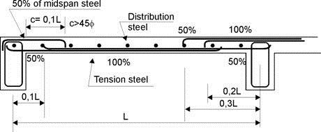
As can be seen from the figure-2 below, the tension reinforcement are 100% at the mid-span of the beam and slab, while it is curtailed at the distance of 0.1 L from the center of the support at end support and 0.2L at the intermediate support. L is the effective length of the beam and slab.
The shear reinforcements are provided from the support to the distance of 0.1L from the face of support on end support and at a distance of 0.3L from the center of support at intermediate support.
Reinforcement Details of Continuous Beams and Slabs
Fig.2: Curtailment of reinforcement in beam and slab construction

3. Typical reinforcement detail for concrete beam

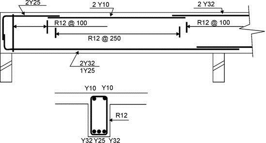
The typical reinforcement details of a concrete beam shall indicate the number of reinforcements, diameter and length of reinforcement for both top and bottom reinforcements.
Typical reinforcement detail for concrete beam
Fig.3: Typical reinforcement detail for concrete beam

Types of Concrete Beams and their Reinforcement Details


Reinforced concrete beams are structural members that support the transverse load which usually rest on supports at its end. Girder is a type of beam that supports one or more smaller beam.

Types of Concrete Beams

Beams are classified as
  1. Simple Beam
  2. Continuous Beam
  3. Semi-Continuous Beam
  4. cantilever beam
  5. T- beam

1. Simple Concrete Beams

Simple concrete beam refers to the beam having a single span supported at its end without a restraint at the support. Simple beam is sometimes called as simply supported beam. Restraint means a rigid connection or anchorage at the support.
Simply supported beam
Fig: Simply supported beam

2. Continuous Beam

It is a beam that rest on more than two supports. It can be a single beam provided for long span between columns or walls with intermediate supports of smallar beams or a single continuous beam for entire length of the structure with intermediate column or wall supports.
Continuous beam with reinforcement details
Fig: Continuous beam with reinforcement details

3. Semi-Continuous Beam

Refers to a beam with two spans with or without restraint at the two extreme ends.
Semi-continuous beam
Fig: Semi-continuous beam

4. Cantilever Beam

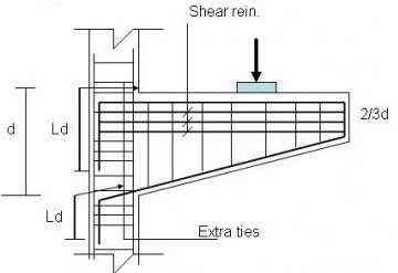
Cantilever beams are supported on one end and the other end projecting beyond the support or wall.
RCC Cantilever beam reinforcement details
Fig: RCC Cantilever beam reinforcement details

5. T – Beam

When floor slabs and beams. are poured simultaneously  producing a monolithic structure where the portion of the slab at both sides of the beam serves as flanges of the T-Beam. The beam below the slab serves as the web member and is sometime called stem.
RCC T-beam
Fig: RCC T-beam