Thursday, July 12, 2018

Calculate Earthquake Forces on Buildings and Structures


Earthquake resistant design requires calculation of earthquake forces on buildings and structures. The guide to earthquake resistant design of building and structures are given by IS 1893:2002 in India.
In this article, how to calculate the earthquake forces for buildings and structures as per IS 1893:2002 code is discussed.

Calculate Earthquake Forces on Buildings and Structures

First step to calculate earthquake loads on structure is to identify the earthquake zone for which structure needs to be designed. This earthquake zones are displayed in a map on page – 6 of the code.
After earthquake zone has been identified, the following steps are followed:
1. Calculate design horizontal seismic coefficient, Ah, which is given by (cl. 6.4.2 of IS1893 – 2002:
Where, Z is the zone factor, given in table 2 of IS1893 – 2002.
I is the importance factor of the structure depending on the function or use. This factor can be obtained from table 6 of the code.
R is response reduction factor. This value is obtained from table 7 of the code. The value of 1/R shall not be more than one.
Sa/g is average response acceleration coefficient. This value depends on time period of structure and on soil type. This can be obtained from clause 6.4.5 of the code.
2. Calculate design seismic base shear for the structure (VB). This is the total design lateral force along any principal direction. This is calculated as:
VB = Ah x W
Where Ah = horizontal seismic coefficient as calculated above in step 1.
W = Total weight of the structure.
3. Now calculate the distribution of design forces on the structure. The seismic design base shear calculate in step above is distributed on the structure as design seismic forces. This is calculated as below:
Where Q= Design lateral force at floor i
W= seismic weight of the floor i
h= height of the floor i from the base
n = number of storeys of the building at which masses are located.
4. Distribution of horizontal seismic forces on structure: These forces are distributed on the vertical elements of the building resisting lateral forces.

Example:

Consider a two-bay two-storied building for which earthquake forces need to be calculated. Consider total weight of the building as 1000 kN. Top roof has the weight of 200 kN and both floors have weight of 400 kN as shown in figure below. The calculation of earthquake seismic forces will be as shown below:
Building Structure Model
Total Weight of the Structure
Wi =
1000
kN
Zone Factor (Zone IV)
Z =
0.24
Importance factor (Table6)
I =
1
Response Reduction Factor
R =
3
Average response acceleration coefficient
Let time period
 T
0.373358
(Cl. 7.6)
Sa/g
2.5
Design Horizontal Seismic coefficient Ah
0.10
Base Shear
100
kN
Storey
Base Shear
Height
Wi
Wixhi2
Qi
Design Force
3
100
8.5
200
14450
57.00197
9.50
2
100
5
400
10000
39.44773
6.57
1
100
1.5
400
900
3.550296
0.59
Total
25350
(in kN)
Earthquake Load on Structure

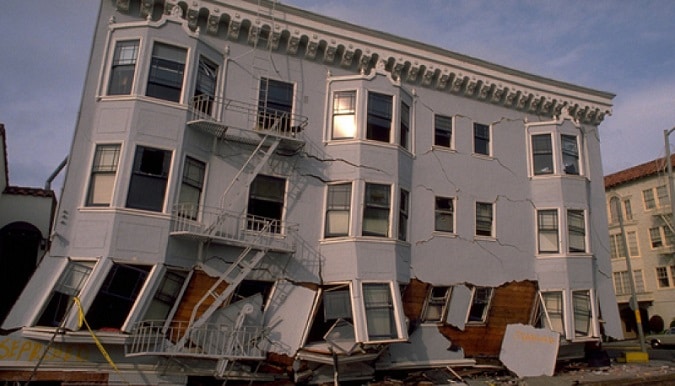
Performance of Various Types of Buildings during Earthquake


Performance of Various Types of Buildings during Earthquake

Different types of buildings suffer different degrees of damage during earthquakes and the same has been studied here.

1. Mud and Adobe Houses during Earthquakes

Unburnt sun dried bricks laid in mud mortar are called adobe construction. Mud houses are the traditional construction, for poor and most suitable in view of their initial cost, easy availability, low level skill for construction and excellent insulation against heat and cold. More than 100 million people in India live in these type of houses.
There are numerous examples of complete collapse of such buildings in 1906 Assam, 1948 Ashkhabad, 1960 Agadir, 1966 Tashkent, 1967 Koyna, 1975 Kinnaur, 1979 Indo-Nepal, 1980 Jammu and Kashmir and 1982 Dhamar earthquakes.
It is very weak in shear, tension and compression. Separation of walls at corner and junctions takes place easily under ground shaking. The cracks pass through the poor joints. After the walls fail either due to bending or shearing in combination with the compressive loads, the whole house crashes down. Extensive damage was observed during earthquake especially if it occurs after a rainfall, (Krishna and Chandra, 1983).
Better performance is obtained by mixing the mud with clay to provide the cohesive strength. The mixing of straw improves the tensile strength. Coating the outer wall with waterproof substance such as bitumen improves against weathering.
The strength of mud walls can be improved significantly by split bamboo or timber reinforcement. Timber frame or horizontal timber runners at lintel level with vertical members at corners further improves its resistance to lateral forces which has been observed during the earthquakes.

2. Masonry Buildings during Earthquakes

Masonry buildings of brick and stone are superior with respect to durability, fire resistance, heat resistance and formative effects. Masonry buildings consist of various material and sizes:
(i) Large block (block size >50 cm)-concrete blocks, rock blocks or lime stones
(ii) concrete brick-solid and hollow
(iii) Natural stone masonry.
Because of its easy availability, economic reasons and the merits mentioned above this type of construction are widely used. In very remote areas in Himalayas buildings are constructed of stacks of random rock pieces without any mortar. The majority of new construction use mud mortar, however, few use cement mortar also.

Causes of failure of masonry buildings:

These buildings are very heavy and attract large inertia forces. Unreinforced masonry walls are weak against tension (Horizontal forces) and shear, and therefore, perform rather poor during earthquakes. These buildings have large in plane rigidity and therefore have low time periods of vibration, which results in large seismic force.
These buildings fall apart and collapsed because of lack of integrity. The lack of structural integrity could be due to lack of ‘through’ stones, absence of bonding between cross walls, absence of diaphragm action of roofs and lack of box light action.

Common type of damage in masonry building:

All of them undergo severe damage resulting in complete collapse and pileup ina heap of stones. The inertia forces due to roof or floor is transmitted to the top of the walls and if the roofing material is improperly tied to the wall, it will be dislodged.
The weak roof support connection is the cause of separation of roof from the support and leads to complete collapse. The failure of bottom chord of roof truss may also cause complete collapse of truss as well as the whole building.
If the roof/floor material is properly tied to the top walls causing it to shear of diagonally in the direction motion through the bedding joints. The cracks usually initiate at the corners of the openings. The failure of pier occurs due to combined action of flexure and shear. Near vertical cracks near corner wall joint occur indicating separations of walls.
For motion perpendicular to the walls, the bending moment at the ends result in cracking and separation of the walls due to poor bonding. Generally gable end wall collapses. Due to large inertia forces acting on the walls, the Wythe of masonry is either bulge outward or inward.
The falling away of half the wall thickness on the bulged side is common feature. The bonding stone is found to be effective as in Jammu Kashmir earthquake of August 24, 1980.
Unreinforced dressed rubble masonry (DRM) has shown slightly better performance than random rubble masonry. The most common damage is due to cracks in the walls. The masonry with lower unit mass and greater bond strength shows better performance. The unreinforced masonry as a rule should be avoided as a construction material as far as possible in seismic area.

3. Reinforced Masonry Buildings during Earthquakes

Reinforced masonry buildings have withstood earthquakes well, without appreciable damage. For horizontal bending, a tough member capable of taking bending if found to perform better during earthquakes.
If the corner sections or opening are reinforced with steel bars even greater strength is attained. Even dry packed stone masonry wall with continuous lintel band over openings and cross walls did not undergo any damage.

4. Brick-Reinforced Concrete Frame Buildings during Earthquake

This type of building consists of RC frame structures and brick lay in cement mortar as infill. This type of construction is suitable in seismic areas.

Causes of failure of RC frame buildings:

The failures are due to mainly lack of good design of beams /columns frame action and foundation. Poor quality of construction inadequate detailing or laying of reinforcement in various components particularly at joints and in columns /beams for ductility. Inadequate diaphragm action of roof and floors. Inadequate treatment of masonry walls.

Common type of damage in RC frame buildings:

The damage is mostly due to failure of infill, or failure of columns or beams. Spalling of concrete in columns. Cracking or buckling due to excessive bending combined with dead load may damage the column. The buckling of columns are significant when the columns are slender and the spacing of stirrup in the column is large.
Severe crack occurs near rigid joints of frame due to shearing action, which may lead to complete collapse. The differential settlement also causes excessive moments in the frame and may lead to failure. Design of frame should be such that the plastic hinge is confined to beam only, because beam failure is less damaging than the common failure.

5. Wooden Buildings during Earthquakes

This is also most common type of construction in areas of high seismicity. It is also most suitable material for earthquake resistant construction due to its light weight and shear strength across the grains as observed in 1933 Long beach, 1952 Kern county, 1963 Skopje, and 1964 Anchorage earthquake. However during off- Tokachi earthquake (1968), more than 4,000 wooden buildings were either totally pr partially damaged.
In addition there were failure due to sliding and caving in due to softness of ground. The main reason of failure was its low rigidity joints, which acts as a hinge. Failure is also due to deterioration of wood with passage of time. Wood frames without walls have almost no resistance against horizontal forces.
Resistant is highest for diagonal braced wall. Buildings with diagonal bracing in both vertical and horizontal plane perform much better. The traditional wood frame Ikra construction of Assam and houses of Nicobars founded on wooden piles separated from ground have performed very well during earthquakes. Wood houses are generally suitable up to two storeys.

6. Reinforced Concrete Buildings during Earthquakes

This type of construction consists of shear walls and frames of concrete. Substantial damage to reinforced concrete buildings was seen in the Kanto (1923) earthquake. Later in Niigata (1964), Off-Tokachi (1968) and Venezuela (1967) earthquake it suffered heavy damages.
The damage to reinforced concrete buildings may be divided broadly into vibratory failure and tilting or uneven settlement. When a reinforced concrete building is constructed on comparatively hard ground vibratory failure is seen, while on soft ground tilting, uneven settlement or sinking is observed.
In case of vibratory failure the causes of damage may be considered to be different for each case, but basically, the seismic forces, which acted on a building during the earthquake, exceeded the loads considered in the design, and the buildings did not have adequate resistance and ductility to withstand them. In general these buildings performed well as observed in Skopje (1963) and Kern country (1952) earthquakes.
The shear walls are fond to be effective to provide adequate strength to the buildings. Severe damage to spandrel wall between the vertical openings is observed.
Tilting and singing of reinforced concrete buildings during earthquakes were seen in the Kanto and Niigata earthquakes. Most failed because the dead weights could not be supported after the settling of the ground. Such damage is peculiar to buildings in soft ground, the damage becomes higher in the following order: pile foundation, mat foundation, continuous foundation and independent foundation.
The hollow concrete block buildings with steel reinforcement in selected grout filled cells have shown good performance. The Precast and prestressed reinforced concrete buildings also suffered severe damage mostly because of poor behaviour of joints or supports. The Precast and prestressed element as a rule were not destroyed as observed in 1952 Kern country and 1964 Anchorage earthquakes.
Reinforced Concrete Buildings during Earthquakes

7. Steel Skeleton Building Performance during Earthquakes

Buildings with steel skeleton construction differ greatly according to shapes of cross sections and method of connection. They may be broadly divided into two varieties, those employing braces as earthquake resistant elements and those which are rigid frame structures. The former is used in low building while the later is used in high-rise buildings.
When braces are used as earthquake resistant elements, it is normal to design so that all horizontal forces will be borne by the braces. This type of building is generally light and influence of wind loads is dominant in most cases. However, there are many cases in which the braces have shown breaking or buckling in which joints have failed (Wiegel, 1970).
Steel skeleton construction, particularly the structural type in which frames are comprised of beams and columns consisting of single member H-beams, is often used in high-rise buildings. The non-structural damage is common but none of these building severely damages as observed in 1906 San Francisco earthquake

8. Steel and Reinforced Concrete Composite Buildings during Earthquakes

Steel and Reinforced Concrete Composite Structures are composed of steel skeleton and reinforced concrete and have the dynamic characteristics of both. It is better with respect to fire resistance and safety against buckling as compared to steel skeleton.
Whereas compared to reinforced concrete structures it has better ductility after yielding. As these features are the properties, which are effective for making a building earthquake resistant and are, found to perform better during earthquakes (Wiegel, 1970).

RETROFITTING OF RCC STRUCTURAL MEMBERS


Retrofitting of RCC structural members is necessary to prevent further distress in concrete. The retrofitting of RCC members should start with investigation and diagnosis of cracks and then by applying suitable retrofitting measures. Following are the steps involved in this process:

1. Investigation and diagnosis of cracks:

(i) After the appearance of cracks in RCC structural members, it is necessary to diagnose the root cause of cracks. If it is ascertained that the cracks in concrete has occurred due to corrosion of steel, further field investigation and testing are required such as destructive (core testing) and non-destructive testing (Rebound Hammer, Ultrasonic pulse velocity method and rebar location etc.).
(ii) Determine degree of cracks, spalling of concrete cover and corrosion of steel for each member. Following table gives the classification of crack with crack width:
Crack WidthClassification of crack
Upto 1mmThin cracks
1 to 2 mmMedium cracks
More than 2mmWide cracks
(i) Determine the condition of concrete i.e. porosity, segregation, and thickness and condition of cover.
(ii) Determine the extent of damage to the reinforcement bars.
(iii) Investigation about failure of previous repairs if any.

2. Repair of concrete cracks:

(i) Materials:
Following materials are generally used for repairing of cracks and rehabilitation of RCC structures.
(a) Portland Cement:
  • Cement slurry injections with or without polymers to seal the gaps, pores or cracks.
  • Motor with or without plasticizers for replacement of concrete cover or surface coating.
  • Microcrete: Guiniting / shotcrete as replacement of concrete or cover concrete.
  • Concrete with or without plasticizers as replacement of existing concrete.
(b) Polymer modified concrete (PMC)
Polymer modified concrete or mortars with the help of polymer latex such as acrylates and SBR (Styrene Butadiene Rubber).
(c) Epoxy resins: with or without addition of filler materials such as quartz sand for injection or concrete repairs. Polymer resins with or without addition of filler materials for concrete repairs.
(d) Ferro-cement concrete: Ferro-cement is a composite material of reinforcement (GI woven wire mesh) and cement sand mortar modified with polymers or other chemicals. Ferro-cement concrete is used to replace cover concrete due to rusting.
(e) Selection of material: Selection of materials depends upon test data
Retrofitting of RCC structural member

2. Concrete repair methods:

  • In case corrosion of steel has not started but carbonation of concrete has started and cracks are thin, coating of polymer or epoxy resins or polymer modified mortars prevent / retard entry of moisture, CO2 and O2 etc. such coatings prevent concrete and prevent corrosions for a period of 10 to 15 years.
  • If corrosion has started, following process is adopted:
(i) Remove weak concrete and expose reinforcement all around.
(ii) Clean the rust of steel by wire brushes or sand blasting
(iii) Apply rust removers and rust preventers.
(iv) Provide reinforcement to supplement rusted steel if required with anchorage i.e. shear connectors.
(v) Apply tack coat (bonding coat to provide bond between old concrete and new concrete) of polymer or epoxy based bonding material.
(vi) Use one of the patching technique to restore concrete to the original surface level. Polymer modified mortars are very good. This can be used with or without guiniting.
(vii) Injection of cement slurry or polymer modified slurry or epoxy to fill up pores or internal cracks or honey combing.
(viii) Apply suitable protective coating.
  • In case the condition of original concrete is very bad and injection grouting is not able to rehabilitate the section to take the required loading, RCC Jacketing of concrete section is to be provided.
(i) Provide the required supporting system to the structure.
(ii) Remove weak concrete.
(iii) Clean the surface and clean the rust of steel.
(iv) Apply rust removers and rust preventers.
(v) Provide additional steel all around the section.
(vi) Provide required formwork.
(vii) Provide polymer based bonding coat between old and new concrete.
(viii) Place the concrete of required thickness and grade and workability admixed with plasticizers.
  • Chajjas or other thin members should be completely replaced or repaired with ferro-cement concrete.